Do you have a question about the Fronius PlasmaModule 10 and is the answer not in the manual?
Introduction to the Fronius PlasmaModule 10, encouraging careful reading of the manual and safety rules.
Explanations of danger signal words (DANGER, WARNING, CAUTION, NOTE) and important notes used in the manual.
General safety remarks, user qualifications, and guidelines for maintaining safety warnings on the machine.
Defines the intended use of the machine and lists prohibited uses like thawing pipes or starting engines.
Specifies the operating temperature range, relative atmospheric humidity, and air quality requirements for the machine.
Details the owner's responsibility to ensure qualified personnel and adherence to safety regulations and manual instructions.
Outlines the obligations of personnel before starting work, including observing regulations and understanding manual instructions.
Explains how high-performance devices affect mains power quality and lists criteria for connection.
Lists hazards during welding such as sparks, radiation, EMF, noise, and fumes, and specifies required protective clothing.
Details protective clothing requirements, ear protection, and measures to keep bystanders away from the welding area.
Provides information on the maximum sound power level generated by the device, noting workplace-specific values are not provided.
Explains the hazards of welding fumes and vapors, their potential health effects, and necessary precautions.
Discusses the harmfulness of welding fumes based on components and advises consulting Material Safety Data Sheets.
Warns about the fire and explosion risks from flying sparks and specifies safety distances and fire prevention measures.
Details the life-threatening risks of electric shock and outlines precautions for handling mains and welding current.
Provides instructions on avoiding electrical hazards, proper grounding, cable management, and safety procedures during maintenance.
Explains the causes and consequences of stray welding currents, including fire and equipment damage, and outlines preventative measures.
Provides additional notes on preventing stray welding currents, especially with automated systems and incorrect torch/wire handling.
Defines EMC emission classes A and B and how they apply to industrial and residential settings.
Outlines measures to prevent or mitigate electromagnetic interference, including mains supply, cable management, and shielding.
Warns about potential health effects of electromagnetic fields and advises on maintaining distance and safe practices.
Highlights specific danger zones such as moving parts, hot workpieces, and areas with fire/explosion risks.
Provides safety instructions for hoisting machines, handling carrying straps, and avoiding hazards from inert gas.
Details the risks associated with shielding-gas cylinders, including explosion hazards, proper handling, and storage.
Covers safety precautions for machine placement, inclination limits, fire/explosion risks, workplace cleanliness, and transportation.
Emphasizes operating the machine only with functional protective features and avoiding manipulation of safety devices.
Reinforces operating with functional safety features, avoiding coolant mixing, and proper disposal procedures.
Advises using original spare parts, obtaining manufacturer permission for modifications, and timely replacement of components.
Recommends annual safety inspections and calibration, performed by qualified electricians, following national standards.
Instructs on proper disposal of the device according to European directives and national laws, emphasizing separate collection.
Explains the meaning of CE and CSA-Test Markings, indicating compliance with relevant safety and compatibility standards.
States the user's responsibility for data security of factory settings and that the manufacturer is not liable for deleted personal settings.
Confirms copyright of the manual, reserves rights for modifications, and requests feedback for improvements or corrections.
Illustrates and describes the control panel of the PlasmaModule 10, including displays, buttons, and LEDs.
Explains the Gas Setup menu for adjusting plasma gas pre-flow time, post-flow time, purging, and pre-flow amount.
Details the Setup menu for adjusting pilot arc current and factory reset functions, and accessing the second level of the menu.
Describes how to access the second level of the Setup menu to configure machine pre-sets like flow monitoring and country settings.
Explains the modular concept of the PlasmaModule 10 and its flexibility in complex welding systems.
Defines 'Plasma' as a gas with charged particles and 'Plasma welding' as a process using a constricted arc.
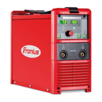
Lists compatible Fronius power sources for the PlasmaModule 10 and notes on cooling units and duty cycles.
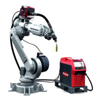
Illustrates and explains the principle of plasma welding, showing the setup with gas regulators, power source, and cooling unit.
Compares plasma welding to TIG welding, highlighting advantages like concentrated arc, smaller HAZ, and longer torch life.
Lists application areas for the PlasmaModule 10, including automated and manual welding in various industries for sheet thicknesses up to 10mm.
Lists available options and accessories for the PlasmaModule 10, such as welding torches, hosepacks, and holders.
General warning about incorrect operation causing injury or damage, emphasizing the need to read operating and safety instructions.
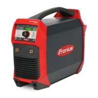
Illustrates the front panel of the PlasmaModule 10, labeling its various controls and indicators.
Provides detailed descriptions of each component on the front panel, including digital displays, LEDs, and buttons.
Illustrates the rear panel of the PlasmaModule 10, labeling connections for LocalNet, plasma gas, and mains.
Details the connections and components found on the rear panel of the PlasmaModule 10.
General warning about incorrect operation causing injury or damage, emphasizing the need to read operating and safety instructions.
Specifies the intended use of the PlasmaModule 10 with TIG power sources and lists supported plasma welding processes.
Describes setup regulations, including IP23 protection, avoiding direct wetting, and placing the machine on a stable surface.
Explains the mains voltage requirements and the importance of properly fitted mains cables and adequate fuse protection.
States that the PlasmaModule 10 is generator-compatible and specifies the minimum apparent power requirement.
Details the digital plasma gas regulator, its safety warnings regarding gas hazards, and proper installation and usage.
Lists factors influencing plasma welding system installation, such as application, material, space, and environmental conditions.
Provides a warning about electric shock during installation and a caution about falling equipment, advising on component setup.
Illustrates and describes the process of connecting the interconnecting hosepack to a TransTig power source.
Illustrates the connection of the interconnecting hosepack to TransTig 4000/5000 power sources and cooling units.
Illustrates how to connect the plasma welding torch to the PlasmaModule 10 and its holder.
Provides instructions for connecting separate cylinders for plasma and shielding gas, specifying pressure and gas types.
Explains the requirements for robot control, including a robot interface and connecting cables to the PlasmaModule 10 and TIG power source.
Details the step-by-step process for commissioning, including electrode insertion, gas purging, and starting the plasma welding process.
Provides operational notes to reduce wear, such as keeping the pilot arc burning and ensuring adequate shielding gas flow.
Illustrates the plasma welding process, showing timelines for welding current and gas flow, including pre-flow and post-flow.
Explains that the Setup menu allows adaptation of saved parameters for different tasks and defines Gas Setup and Setup menu parameters.
Guides users on entering the Gas Setup menu to adjust plasma gas pre-flow time, post-flow time, and gas purging.
Details the GPA parameter for plasma gas pre-flow and post-flow amount.
Guides users on entering the Setup menu to adjust plasma process parameters like pilot arc current and factory reset.
Explains how to access and enter the second level of the Setup menu for machine pre-set parameter configuration.
Details how to select and change parameters in the second level of the Setup menu, and how to exit.
Lists and describes machine pre-set parameters such as Flow monitoring (C-C), Gas correction (COr), Country setting (SEt), and Ignition Time-Out (ItO).
Provides a table of correction factors for various plasma gas compositions, including Argon, Helium, and Hydrogen mixtures.
States that robot operation of the PlasmaModule 10 requires a robot interface and lists available control interfaces.
Presents an overview table mapping signals (Input/Output) to different robot interfaces (ROB 3000, ROB 4000, Field bus).
Describes the function of various signals for robot-controlled plasma welding, including welding start, robot ready, and arc stable.
Details the 'Power source ready' and 'Welding current real value' signals for robot operation.
Illustrates the signal waveforms for power input, robot ready, welding start, arc stable, and power source ready signals over time.
Provides an example of how to connect the robot interface to the robot control, detailing signal assignments and wiring.
Warns about unexpected welding starts and the effect of connection loss on output signals, and explains voltage selection for digital outputs.
Mentions the intelligent safety system, fuse-less operation, and safety precautions before opening the machine.
Lists specific service codes (tP1, tS1, tSt, Err 051, Err 052) and their causes and remedies.
Lists further service codes (no | IGn, Err | IP, Err | bPS, dSP, no | Arc, no | H2O, -St | oP-, Err | 70.1, no | GAS, Err | 70.3) and their causes and remedies.
Lists remaining service codes (Err | 70.4, Err | 70.5) and general troubleshooting for 'No function' and 'No pilot arc'.
Emphasizes minimum care and maintenance for long-term usability and lists safety precautions before opening the machine.
Details checks to perform at every start-up, including mains plug, torch, hosepack, earth connection, and cooling air flow.
Suggests cleaning the air filter every 2 months and cleaning the machine interior every 6 months.
Instructs on proper disposal of the machine in accordance with applicable national and local regulations.
Illustrates the 'Manual mode' configuration for a plasma welding system for manual use.
Provides a list of components used in the 'Manual mode' configuration, with corresponding item numbers.
Illustrates the 'Robot mode' configuration for a plasma welding system for automated use.
Provides a list of components used in the 'Robot mode' configuration, including robot interfaces and cables.
Notes that inadequately dimensioned electrical installations can cause damage and that rating plate data applies.
Lists key technical specifications such as mains voltage, tolerance, fuse protection, power, current range, voltages, protection class, and dimensions.
Part identification numbers and labels for components of the PlasmaModule 10.
Lists part numbers and corresponding components for the PlasmaModule 10, with explanatory notes in multiple languages.
Continues the spare parts list for the PlasmaModule 10, detailing components with their respective part numbers and labels.
| Brand | Fronius |
|---|---|
| Model | PlasmaModule 10 |
| Category | Welding System |
| Language | English |