Brief description
Safety
WARNING!
Danger from incorrect operation and work that is not carried out properly.
This can result in serious personal injury and damage to property.
▶
All the work and functions described in this document must only be carried
out by technically trained and qualified personnel.
▶
Read and understand this document in full.
▶
Read and understand all safety rules and user documentation for this device
and all system components.
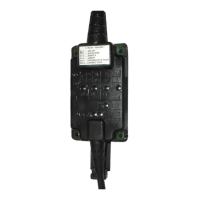
General remarks The ROB I/O fieldbus extend module enables the 2 MB Interbus to send and re-
ceive additional external signals.
The ROB I/O has a pre-assembled cable harness for linking it to the automatic-
welder control system. At the control-system end of the cable harness, it is pre-
fabricated with a lamp-wire connector.
NOTE!
To avoid malfunctions, the length of the cable between the ROB I/O and the
control system must not be more than 1.5 m.
Digital inputs
and outputs
WARNING!
Electric shock hazards.
This can result in serious personal injury.
▶
Do not use the ROB I/O extend module to control mains-powered compon-
ents.
4 digital input signals and 2 digital output signals are available on the bus.
The digital inputs and outputs are galvanically separated
-
from one another
-
from the LocalNet and the welding potential
-
for a maximum voltage difference of 100 V
Process data
width
The ROB I/O module enables the 2 MB Interbus to transfer 112 bit wide instead
of 96 bit wide process data. As a result, additional input and output signals are
available on the 2 MB Interbus.
IMPORTANT! The 112 bit wide process data width is only available:
-
if the ROB I/O module has been connected to the power source Interbus
control prior to energising the Interbus control
-
as soon as the system recognises the ROB I/O module
16