Output signals
from the robot to
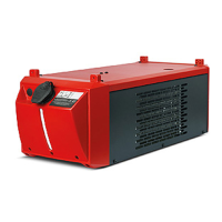
the power source
Seq. no. Signal designation Field Activity
A01 Current-flow signal
(with active welding arc)
- High
A02 Limit signal (with RCU 5000i) - -
A03 Process active - High
A04 Main current signal - High
A05 Torch collision protection - High
A06 Power source ready - High
A07 Communication ready - High
A08 Reserve - -
A09 Error number bit 0 (value 1) - High
A10 Error number bit 1 (value 2) - High
A11 Error number bit 2 (value 4) - High
A12 Error number bit 3 (value 8) - High
A13 Error number bit 4 (value16) - High
A14 Error number bit 5 (value 32) - High
A15 Error number bit 6 (value 64) - High
A16 Error number bit 7 (value 128) - High
A17 - A24 Unused - Low
A25 Wire stick control - High
A26 - A32 Unused - -
A33 - A48 Actual value: welding voltage 0 - 65535 0 - 100 V
A49 - A64 Actual value: welding current 0 - 65535 0 - 1000 A
A65- A72 Actual value: motor current 0 - 255 0 - 5 A
Pulse correction
A73 - A80 Unused - -
A81 - A96 Actual value: wire feeder 0 - 65535 0 - 22 m
A97 Output 1 - 0 - 22 m
A98 Output 2 - -
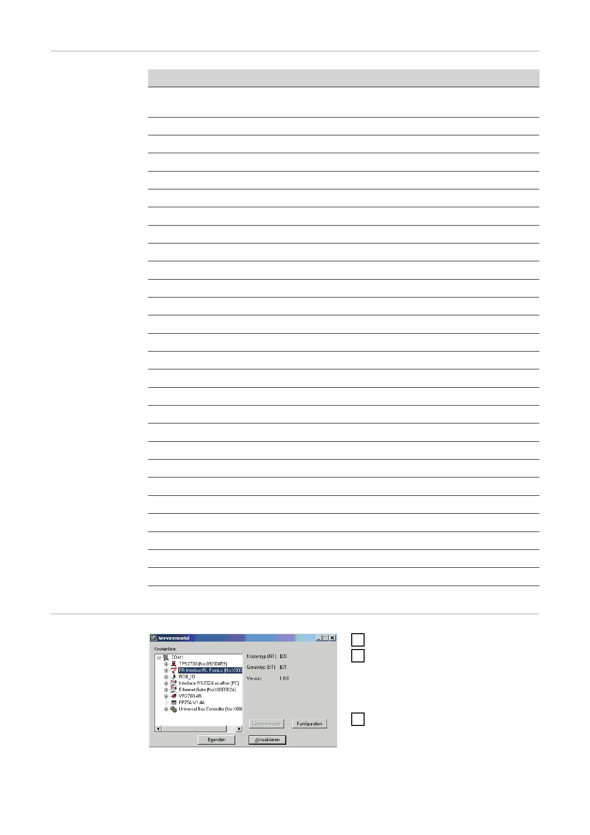
How to configure
ROB I/O
1
Open Service Module software
2
On the Service Module screen
(node list), mark the item „FR In-
terbus-RL Fronius ...“
-
The Configuration button is
activated
3
Click the Configuration button
The Configuration Fieldbus dialog box opens.
18