Mounting ROB I/O
Safety
WARNING!
Danger from incorrect operation and work that is not carried out properly.
This can result in serious personal injury and damage to property.
▶
All the work and functions described in this document must only be carried
out by technically trained and qualified personnel.
▶
Read and understand this document in full.
▶
Read and understand all safety rules and user documentation for this device
and all system components.
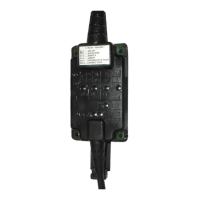
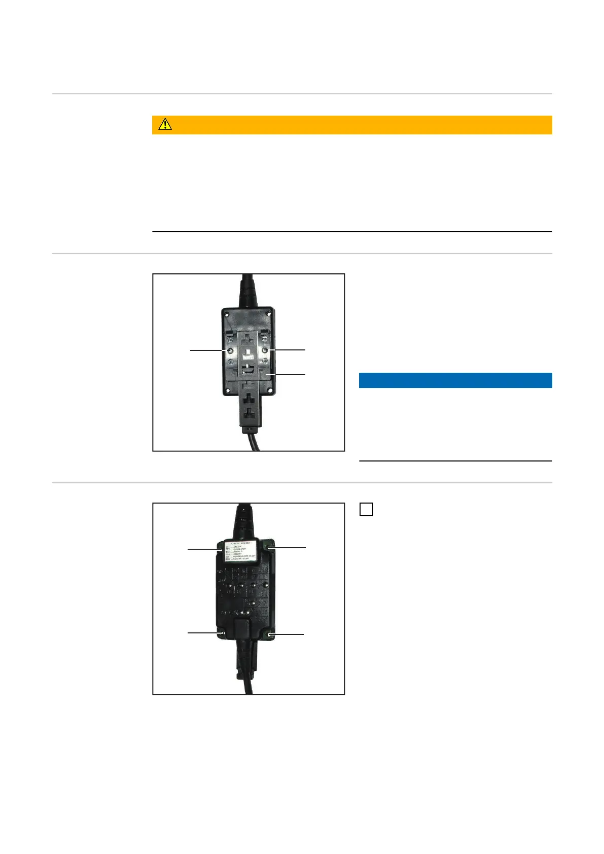
Fasten ROB I/O
via mounting bo-
res
4 Mounting bores Ø 4.2 mm (0.17 in.)
IMPORTANT! When mounting ROB
I/O via the mounting bores (1) the fol-
lowing shall be observed:
-
Use only appropriate screws (dia-
meter of bore Ø 4.2 mm (0.17 in.)
-
Fix always regularly by means of 4
screws
NOTE!
Don’t tighten the screws too much. An
excessive tightening torque may da-
mage the ROB I/O and even lead to
breakage.
▶
Max. tightening torque 0.4 Nm
Fastening the
ROB I/O to the
top-hat rail
Mounting bores Ø 4.2 mm (0.17 in.)
1
Fasten the enclosed top-hat rail
holder (2) onto the robot interface
ROB I/O, using 2 screws (3).
English
23