Version 1:
externe 24 V
Ansteuerung
Version 2:
Potentialfrei
(Klemme 1/3)
(Klemme 1/11)
+ 24 V von der
Automatensteuerung
V
DC
(intern)
max. 100 V
GND extern GND input GND input
GND uP
uP
V
DC
(intern)
(Klemme 1/10)
(Klemme 1/11)
max. 100 V
uP
GND uP
GND inputGND input
Klemme 1/3 ........ HI Input 2
Klemme 1/11 ...... GND Input 2
Klemme 1/10 ..... LO Input 2
Klemme 1/11 ..... GND Input 2
Automat
Stromquelle
(3)
(3)
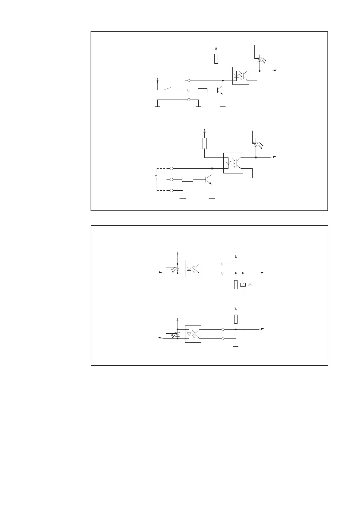
Eingangssignale Feldbus-Erweiterung ROB I/O
Version 2:
„Low-aktiv“
Version 1:
„High-aktiv“
+ 24 V von der
Automatensteuerung
+ 24 V von der
Automatensteuerung
(Klemme 2/15)
(Klemme 2/16)
(Klemme 2/15)
(Klemme 2/16)
+ 24 V von der
Automatensteuerung
+ 24 V von der
Automatensteuerung
+ 24 V
DC
/ 20 mA
+ 24 V
DC
/ 20 mA
uP
uP
Klemme 2/16 ...... Supply Output 1
Klemme 2/15 ...... Output 1
Klemme 2/16 .... Supply Output 1
Klemme 2/15 .... Output 1
Stromquelle Automat
max. 100 V
max. 100 V
(9)
(9)
Ausgangssignale Feldbus-Erweiterung ROB I/O
Deutsch
9