24
Pin assignment of
the option plug
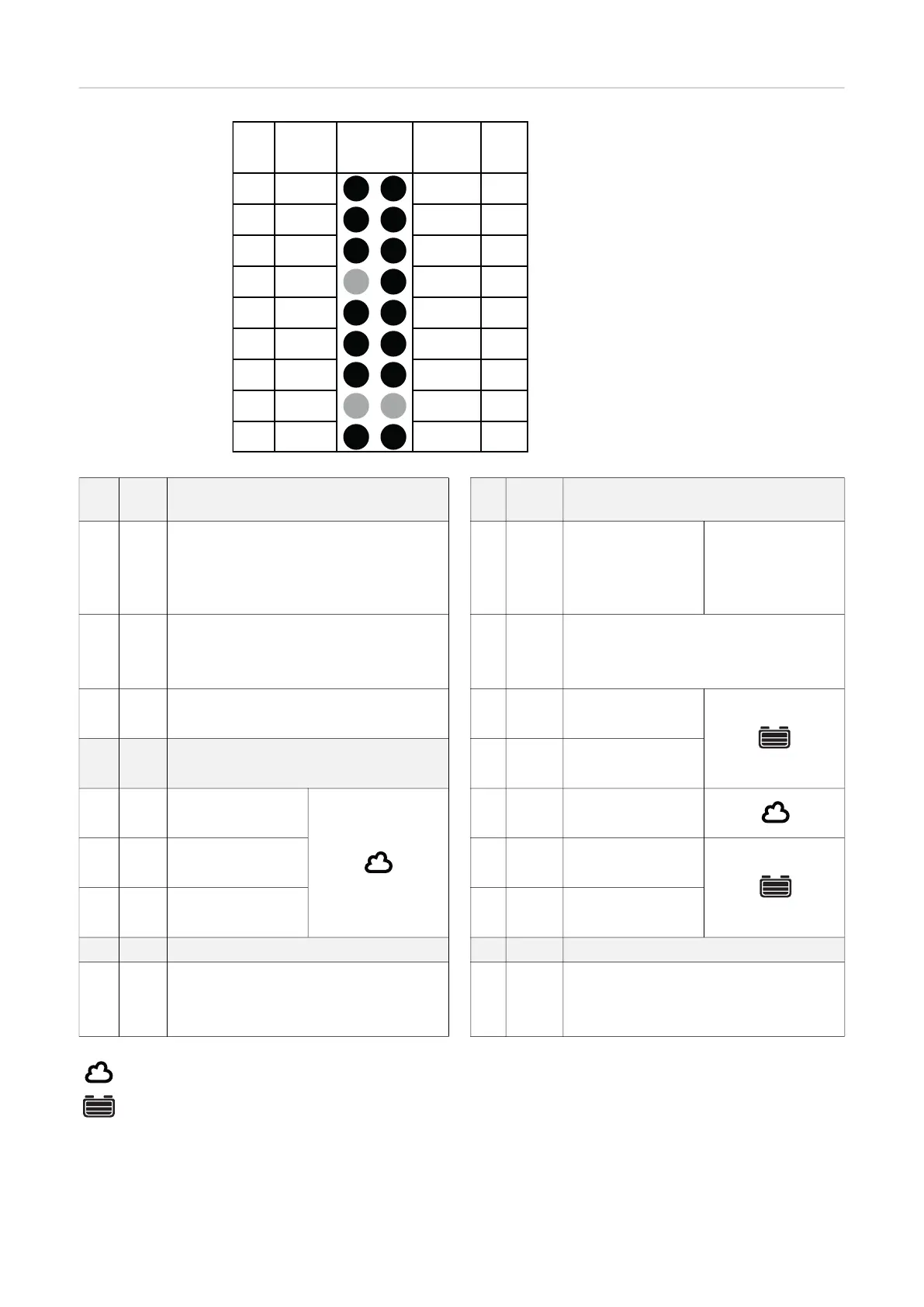
Connections of the 18-pin option plug
on the P-Control PC board inside the
housing
17 G / 2 13V / 1
Y / 3 R / 4
B Dete
C2 G
C1 G 13V O
C1 L C2 L
C1 H C2 H
- St + St
Pin Pin
Plug
Code
Plug
Code
Plug
18p
15
13
11
9
7
5
3
1
18
16
14
12
10
8
6
4
2
Pin Plug
code
Function Pin Plug
code
Function
17 G/2 Ext. LED Green 18 13V/1 13 V Ext. LED
Remote control wire 2 Power supply Remote control
wire 1
CBG Easy VCC
15 Y/3 Ext. LED Yellow 16 R/4 External LED Red
Remote control wire 3 Remote control wire 4
CBG Easy Detect
13 B Ext. LED Blue 14 Dete Detect
CBG Easy GND wire white
11 12 C2 G CAN 2 GND
wire brown
9 C1 G CAN 1 GND 10 13V O 13 V power supply
wire brown wire white
7 C1 L CAN 1 Low 8 C2 L CAN 2 Low
wire yellow wire yellow
5 C1 H CAN 1 High 6 C2 H CAN 2 High
wire green wire green
3 4
1 - St Temperature controlled 2 + St Temperature controlled
Charging Charging
External start/stop External start/stop
Gateway/cloud
Battery link