10
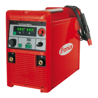
Fig.11 TR 1000 / TR 1100 control panel
(37) Parameter-display button(s) ... for
selecting the parameter to be display-
ed (welding current, ...)
(38) Parameter-setting button(s) ... for
altering the selected parameter
(39) Welding current parameter
(39)
(38)
(37)
(37)
(38)
System requirements:
- Software version 2.81.1
TP 08 remote-
control unit
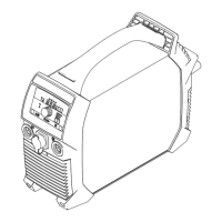
Fig.12 TP 08 remote-control unit
1. With the “Process” button (3), select
the rod-electrode (MMA) welding
process
2. Attach the earth clamp to the workpi-
ece and clamp the electrode holder to
the TP 08 remote-control unit
3. Place the TP 08 down on the workpi-
ece in such a way that there is a
solid, firm connection between the
workpiece and the two contacts (ZL)
(ZP)
(ZQ)
(ZL)
(ZO) (ZN)
(ZM) (ZR)
(ZL)
NOTE! The welding voltage is switched to the welding sockets after a 3 sec
time-lag. The TP 08 remote-control unit is then supplied with welding voltage,
and indicator (ZM) lights up.
If the TP 08 remote-control unit has been connected up since the power source was
last switched on, it is only possible to set the amperage and arc-force dynamic on the
TP 08 remote-control unit.
To make it possible to set the amperage and the arc-force dynamic from the power
source once again, as well as from other system add-ons:
- Disconnect the TP 08
- Switch off the power source, then switch it back on again
TR 1000 / TR
1100 remote-
control unit
(continued)
 Loading...