18
Tungsten electrode
Spot-weldGas discharge openings
Spot-welding gas nozzle
Fig. 22
Note! In the event of any trouble, the welder can manually
interrupt the automatic spot-welding sequence by pulling
back and releasing the trigger again!
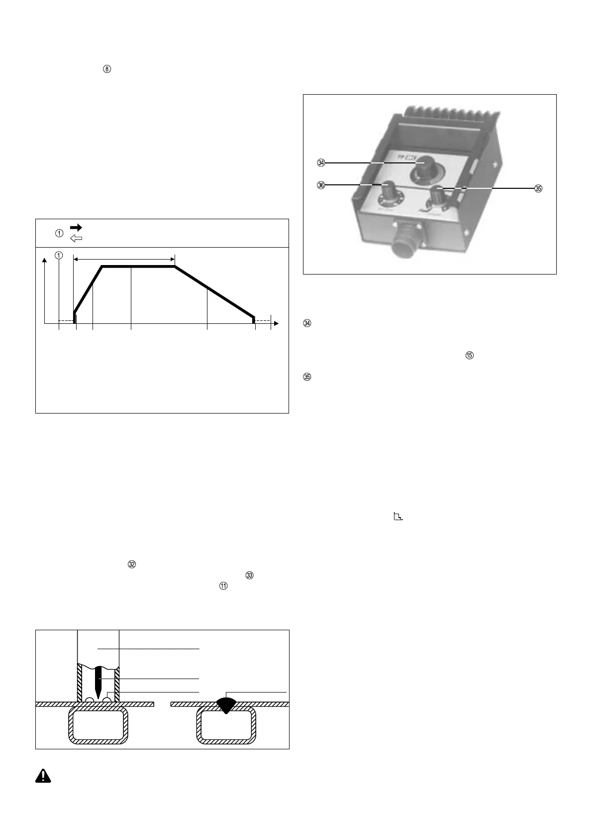
TPmc REMOTE CONTROL UNIT
This workplace remote control unit is intended for use in particular
with manual electrode and TIG welding.
(Magnet, for attaching the remote control unit to the workpiece)
Functional description:
- The machine automatically switches over to 2-step operation
- LED indicator
lights up
- The current drop time is set directly on the power source
- A special - insulated - spot-welding nozzle is used, which is
mounted on the cone.
- Depending on the size of spot-weld required, mount the tungs-
ten electrode approx. 2 - 3 mm back from the edge of the nozzle
(Fig. 22).
- Set the spot-welding current and time on the remote-control
unit.
- Place the torch (i.e. the spot-welding nozzle) on the workpiece
(Fig. 22).
- To carry out the spot-weld, gently press down onto the base
material and actuate the torch trigger.
(Make sure there is no air-gap!)
Pull back and release the torch trigger
Fig.21
Start of cycle
Gas pre-flow time
Current-rise via up-slope
Gas post-flow time
End of welding
Arc ignition
Spot welding with pre-
set welding current I
H
and spot time t
H
Current-drop
via down-slope
The automatic spot-welding sequence is as follows:
- Pull back and release the torch trigger.
- Gas pre-flow time elapses.
- Arc ignites with start-arc current.
- Current rises via the set up-slope to the spot-welding current
value set on the dial
.
- The spot-welding time (0,5 - 8 secs.) set on the dial
elapses.
- The current drops via the down-slope (dial
) to a minimum
current value of 3A over the period of time set, and then
switches off.
- The gas post-flow time elapses.
Fig.23
WELDING CURRENT DIAL = Main current I
H
For continuous adjustment of the welding current from 3 / 5 to
200A (TIG) resp. 3 to 180A (Electrode)
(see also the description on p. 11, Pt. )
ARC FORCE CONTROL DIAL
Influences the short circuit amperage at the moment of drop
transfer (from electrode to workpiece)
At scale setting "0" TIG there is no increase at all in the short
circuit amperage at the moment of drop transfer (soft arc)
Range of application:
- TIG-DC welding
- Welding using rutile electrodes (fine globules)
- Basic sheathed electrodes in the medium and upper amperage
ranges
- Caution! When welded at low load, basic-sheathed electrodes
tend to "GET STUCK" on the workpiece.
At scale setting "10" there is a very considerable in-
crease in amperage at the moment of drop transfer (hard arc)
Range of application:
- Basic sheathed electrodes (coarse-globule), when these are to
be welded in the lower amperage range (vertical-up seams,
edge hardfacing welds, root welding etc.)
Practical tips!
When the setting on the arc force control dial is adjusted upwards,
the following may be observed when rutile, basic-sheathed or
special electrodes are being used:
- Easy ignition
- Reduction in welding misfires
- Less electrode burn-on
- Good root penetration
- Occasionally an increase in spattering
- When welding thin sheet metal the danger of "burning through"
increases
- With filling-welds, there will be a tendency for the arc to become
somewhat harder
- With fine-globule electrodes (titanium) the above will not be
observed, as metal transfer occurs without a short circuit being
produced.
I
t
I
H
t
H