12
b) DC-operation:
- Is used to set the ignition current for the diameter of tung-
sten electrode in question.
When the machine is in the “Electrode" modes, adjustment
dial
is inactive.
SELECTOR SWITCH for TYPE OF CURRENT:
/ /
This is used for selecting the type of current required, and for
reversing the polarity with both TIG and ROD ELECTRODE
MANUAL WELDING.
Functional description:
1. : (=> TIG welding of unalloyed, low and high alloy
steels, Sn or Cu bronzes, copper etc.)
a) TIG mode => LED or lights up
- Minus pole is on the tungsten electrode
b) MAN.ELECTRODE mode => LED lights up
- Minus pole is on the rod electrode
2. : (=direct current => special TIG welding)
a) TIG mode= LED or lights up
- The minus pole is on the tungsten electrode
Warning! An electronic interlocking, fitted as standard,
prevents the plus-pole from being switched to the tungsten
electrode in the TIG mode, as this would overload and
damage the electrode.
b) MANUAL ELECTRODE mode => LED lights up
- The plus pole is on the rod electrode
(interlocking is automatically made inoperative).
3. (=alternating current, TIG welding of aluminium
and its alloys, aluminium-bronze etc.)
a) TIG mode => LED or lights up
- Alternating current is on the tungsten electrode
b) MANUAL ELECTRODE mode => LED lights up
- Alternating current is on the rod electrode
The following parameters are laid down by an internal program:
- Gas pre-flow time ............... 0.4 sec
- Start arc:
36 % of I
H
in DC mode
50 % of I
H
in AC mode
- Up-slope ............................. 1.0 sec
- Gas post-flow time .............. 5 - 15 sec, dep. on amperage
- Frequency .......................... 60 Hz
All parameters can be changed individually, via a program menu.
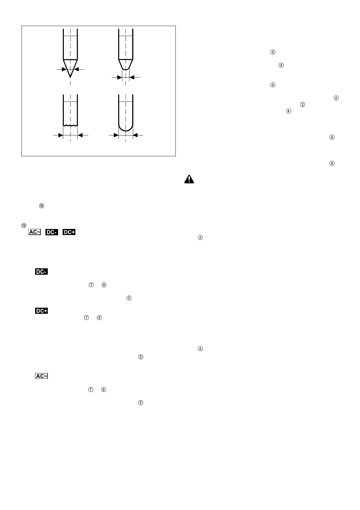
Fig. 10 Diagram showing formation of spherical tip
after ignition
before ignition
1. ACCESSING THE VARIOUS PROGRAM
LEVELS
1.1 Pre-setting level:
Press function selector switch
, switching the machine on
at the same time. As soon as 3 lines appear in the display,
stop pressing the selector switch
.
1.2 Level 1:
Press function selector switch
, switching the machine on
at the same time. As soon as 3 lines appear in the displays,
press the torch trigger once, keeping the selector switch
pressed. “P1” will appear on the ammeter .
-> Stop pressing the selector switch
1.3 Level 2:
Proceed as for Level 1, but press the torch trigger twice.
Display shows “P2”. Stop pressing the selector switch .
1.4 Level 3:
Proceed as for Level 1, but press the torch trigger 3 times.
Display shows “P3”. Stop pressing the selector switch .
Caution! Before you access the pre-setting level (as per 1.1
above), check whether the machine is in the “TIG” or “Elec-
trode” mode. The parameters shown will be those for the
operating mode in which the machine happens to be.
2. PARAMETERS
2.1 TIG pre-setting level:
All parameters can be selected with function selector switch
, and then changed with the torch trigger.
- GAS Gas pre-flow 0.2 - 2 sec
- G-L Gas post-flow at I
min
2.0 - 26 sec
- G-H Gas post-flow at I
max
2.0 - 26 sec
- UPS Up-slope 0.2 - 7 sec
- SCU Starter current
(start arc 10 - 100 % in DC, 30 - 100 % in AC)
- I3 Reduced current, 0-100% of I
H
- StS Special 2-step mode ON/OFF
- SFS Special-4-step mode OFF/1/2
- PRO (Program): For storing the parameters, once these
have been set, by pressing the torch trigger forward.
- FAC (Factory): For activating the parameters pre-set by
Fronius, by pressing the torch trigger forward.
2.2 “Electrode” pre-setting level
All parameters can be selected with function selector switch
, and then changed with the torch trigger.
- Hti Hotstart time 0.2 - 2 sec
- HCU Hotstart current 0 - 100 %
- dYn Arcforce dynamic 0 - 100 A
- PRO (Program): For storing the parameters, once these
have been set, by pressing the torch trigger forward.
- FAC (Factory): For activating the parameters pre-set by
Fronius, by pressing the torch trigger forward.
- In the “Electrode AC” mode, the applicable frequency is
the one set in Level 3. The waveform in “Electrode AC” is
generally a square-wave one.
Parameters of the pre-set Fronius program:
GAS 0,4sec Hti 0,5sec
G-L 5,0sec HCU 50%
G-H 15,0sec dyn 30A
UPS 1,0sec ACF 60Hz
SCU DC 36% POS sin
AC 50% nEG rEC
SFS OFF I3 50%
StS OFF