11
ENGLISH
- LED indicator lights up
The digital ammeter indicates the command value for cur-
rent as soon as the machine is in open circuit, and then
switches over to an indication of the actual value.
Command value -> desired welding current
Actual value -> actual welding current
CRATER-FILL CURRENT: I
E
- Only possible in 4-step operation
- Is set as a %-age of the main current
- The welding current is lowered to the crater-fill current when
the torch trigger is pressed. LED control light indicates
that this is taking place, and stays lit up until the end of the
pre-set crater-fill time.
BALANCE DIAL /
- For influencing the positive and negative half-wave. This
enables the welder to adapt to the welding problem in hand
by optimizing the cleaning and penetration relationships.
- For influencing the loading of the tungsten electrode =
optimization of the shape of the cap formed on the electrode
tip (Fig. 9c)
- Only functions in the AC~ range, in the / and
positions (dial is automatically made in-operative when
the machine is switched over to the DC range).
Examples of settings:
(Welding current is set to a given value)
a) Balance dial is in position "0" on scale:
Neutral setting
b) Balance dial is in position "+5" on scale:
i.e. the positive half-waves are longer than the negative
ones = long cleaning phase but reduced penetration depth;
increased load on tungsten electrode - cap formed on
electrode tip is too large (Fig. 9b) - risk of tungsten inclusions
in the welding pool due to drops being shed by the over-
heated electrode.
c) Balance dial is in position "-5" on scale:
i.e. the negative half-waves are longer than the positive
ones = long penetration phase but reduced cleaning effect;
tungsten electrode is underloaded (Fig. 9a) - no cap formed
on electrode tip - arc not central - generally unstable.
LED INDICATOR FOR 2-STEP MODE
2-step mode
- Activated from TIG torch trigger
- Mainly used for tack welding
- In the "PRESETTINGS LEVEL___" program level (TIG
parameters), StS must be set to OFF
Functional sequence:
1. Pull back and hold trigger
- Gas pre-flow time elapses
- Arc ignites with start-arc current (HF cuts out automatically
after the ignition cycle)
- After ignition, the welding current rises via the internally pre-
set upslope to the welding current I
H
- LED lights up
2. Release trigger
- Arc goes out (with or without downslope)
- Internally pre-set gas post-flow time elapses
If a TR 52mc pedal remote-control unit is being used, the
machine automatically switches over to the 2-step mode.
Special 2-step mode - Variant I
- Activated from TIG torch trigger
- Mainly used for tack welding
- In the "PRESETTINGS LEVEL___" program level (TIG
parameters), StS must be set to ON
Functional sequence:
1. Pull back and hold trigger
- Gas pre-flow time elapses
- Arc ignites
- Welding current rises directly (without upslope) to welding
current I
H
- LED lights up
2. Release trigger
- Arc goes out (without downslope)
- Internally pre-set gas post-flow time elapses
If a TR 52mc pedal remote-control unit is being used, the
machine automatically switches over to the 2-step mode.
DOWN-SLOPE or current drop time
- For continuous adjustment of the current drop speed from
the main current down to the crater-fill current I
E
Range: 0,2 to 20 seconds
LED INDICATOR
HOLD
- The HOLD function (for storing actual values) works in every
operating mode (except for r.c. pedal unit, pulsed-arc wel-
ding using r.c. pedal unit, and pulsed-arc welding up to 20 Hz)
- Display lights up after actual values have been stored - i.e.
the mean of the welding current and voltage values measu-
red before the end of a welding operation is indicated by the
digital displays and , and stored. (This permits subse-
quent checking of the welding parameters).
Ways of deleting the HOLD function:
- Switch the mains master switch off and back on again
- By adjusting the welding current dial during the breaks
between welding
- By shifting the function selector switch
- By shifting selector switch (for choosing between DC+,
DC- and AC~ currents)
- Every time you start welding
- By actuating the torch trigger between welds
MAIN CURRENT DIAL I
H
= welding current
- For continuous adjustment of the welding current over the 3
(or 5) to 200 A range (TIG) and over the 3 - 180 A range
(electrode)
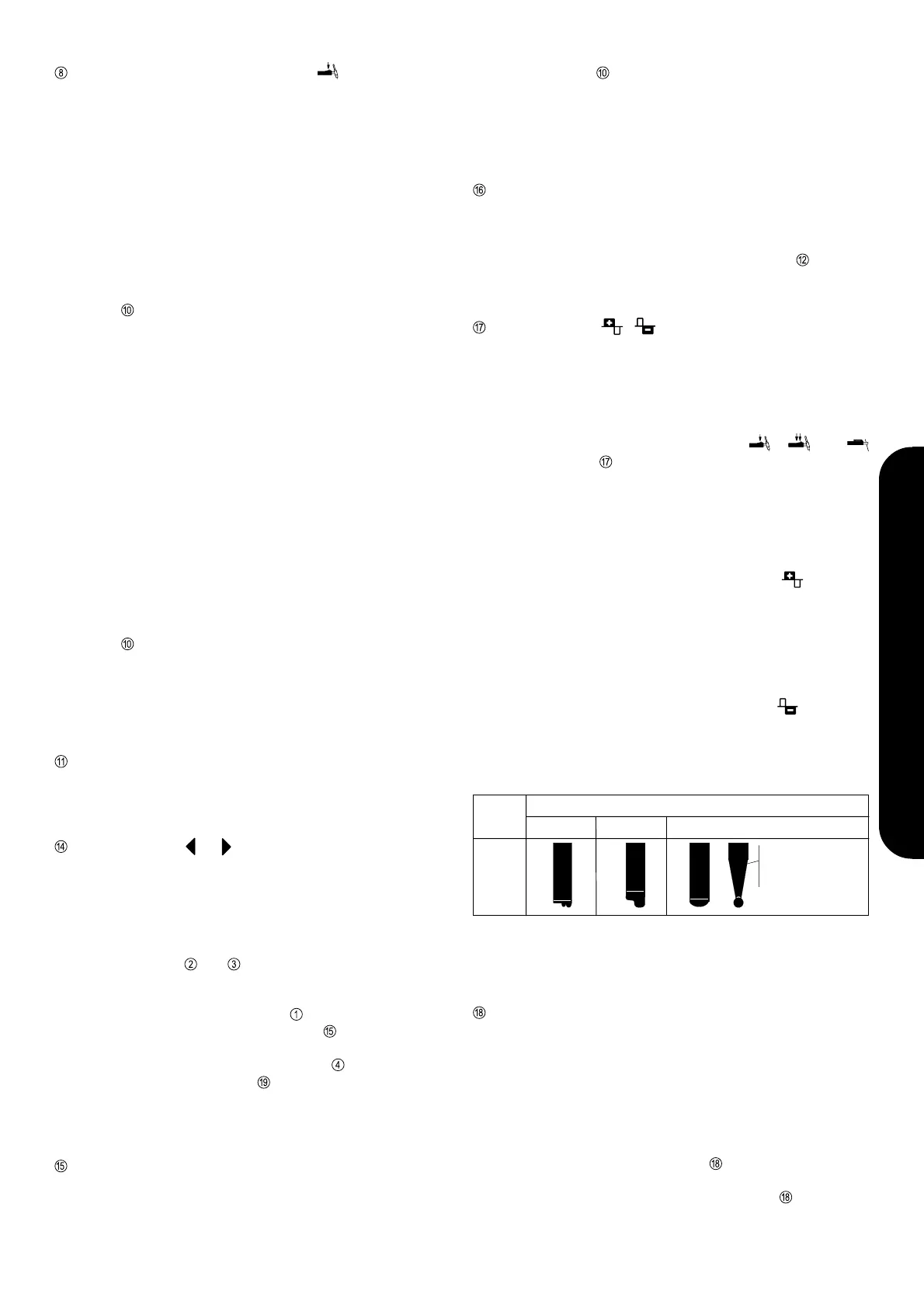
Type of
current
Current load
too low too high
a) b) c)
AC
~
correct
good for
root passes and
thin workpieces
Fig. 9 Shapes of caps formed on tungsten electrodes subjected to different
loads in the AC range
ADJUSTMENT DIAL FOR DIAMETER OF
TUNGSTEN ELECTRODE (0 - 3.2 mm)
a) AC operation:
- For automatic formation of a spherical tip to the tungsten
electrode. Before starting to weld, briefly push the torch
trigger forward and then initiate the welding operation. A
spherical tip is then formed on the - pointed or blunt -
tungsten electrode, as determined by the electrode-diame-
ter value set beforehand on dial .
- If the torch trigger is not pushed forward, dial can be used
to set the ignition current for the diameter of tungsten
electrode in question.