19
33. When done make sure parameter 34210 [0] shows 2 for all axes (axis with motor encoder)
34. When done make sure parameter 34210 [0] and parameter 34210 [1] shows 2 for all axes (axis with scale)
3.32 Check Axis Backlash
Tools Required: 0.0001” resolution dial indicator, remote handwheel (manual pulse generator)
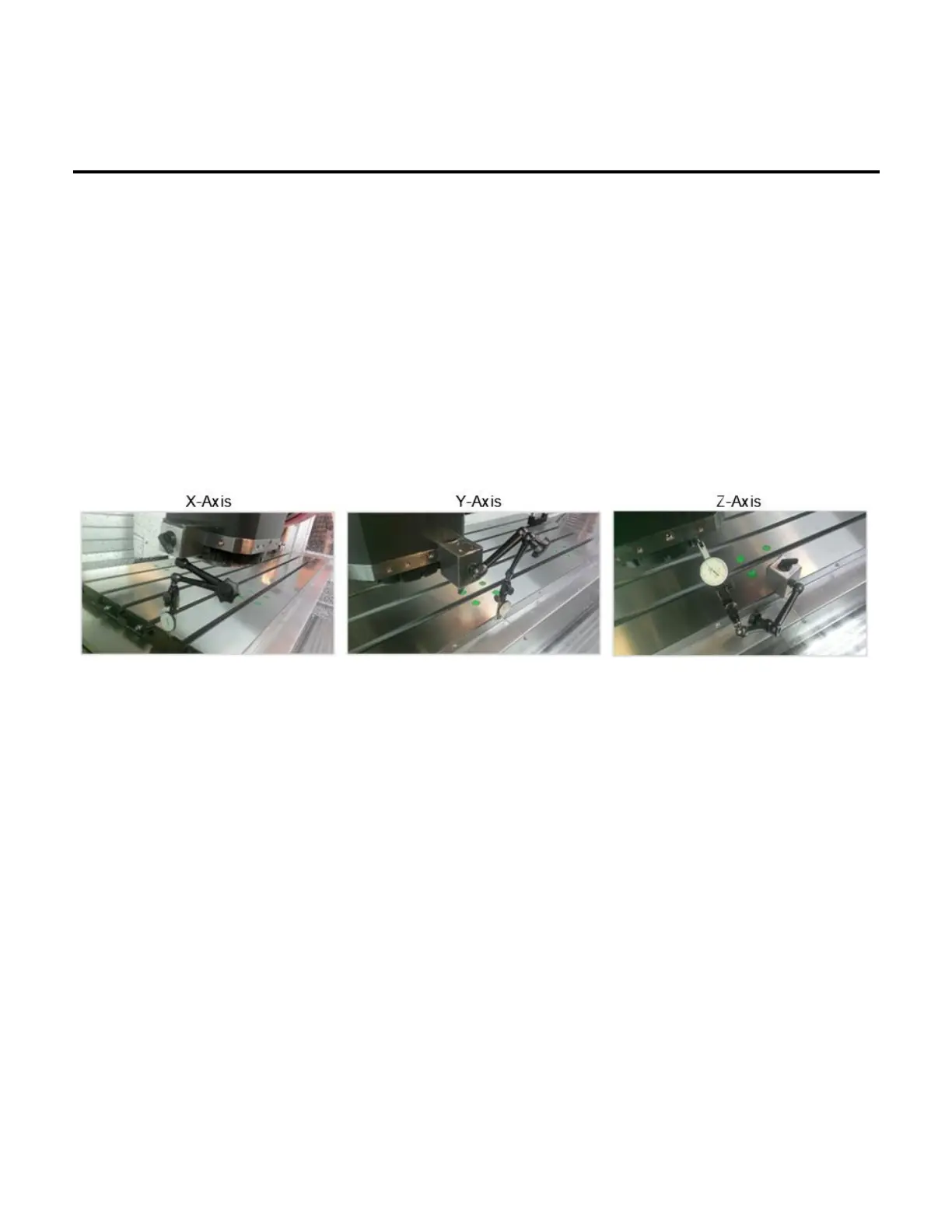
• Set the indicator along the axis which is being measured. The needle should be in contact with a flat
machined surface and the base on a stable, fixed point. See the pictures below which illustrate the setup for
the X, Y, and Z axes.
• Using the remote handwheel, move the axis in one direction either positive or negative until the indicator is
loaded by 0.002”.
• Zero the indicator.
• Move the axis in the same direction by 0.005”.
• Reverse the direction of the axis by 0.005”.
• The additional amount that is needed to reach zero after the 0.005” reverse in direction is the backlash
measured.
• This shows the loss of motion in the axis from the ballscrew and linear guide rails. Backlash compensation
can be adjusted according to the procedure outlined below in Section 3.33.
 Loading...