35
5.16 Spindle Orient Adjustment
PROCEDURE TO BE PERFORMED BY QUALIFIED PERSONNEL ONLY
This procedure will outline how to adjust the spindle orient position when an M19 is commanded to perform a tool
change. Read all instructions carefully and do not skip steps.
1. Put a tool in the spindle, make sure the carousel location in the load position( directly opposite the spindle) is
empty.
2. In MDI clear out any previous commands and type in:
G75 FP=0 Z0
M19
3. Press CYCLE START to execute. Notice the direction the spindle goes in (Forward or Reverse)
4. Press MENU SELECT
5. DIAGNOSTICS
6. AXIS DIAG, (If you do not see key press “>” arrow key to see more buttons.
7. Press SERVICE AXIS
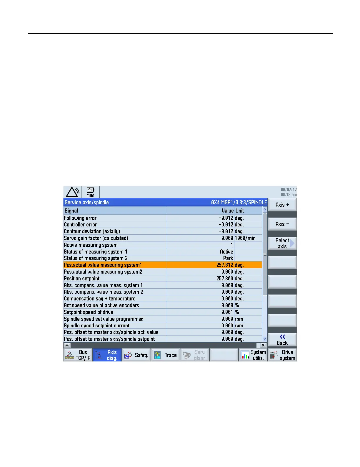
8. Use Axis + or Axis - key to display AX4:MSP1/3.3.3/SPINDLE see screen below:
9. Press RESET and slowly turn the spindle in the direction the M19 orient command turned in step 3, until the
spindle keys line up with the ATC carousel key.
10. Remove the air pressure and push the ATC carousel under the spindle make sure the spindle key is lined up.
While looking at the above screen turn the spindle CW and CCW. Note the max and minimum values of the
Pos. actual value measuring system 1. Calculate the average of the two values. This is the new orient position.
11. Press MENU SELECT
12. Press SETUP
13. Press MACH DATA
 Loading...