19
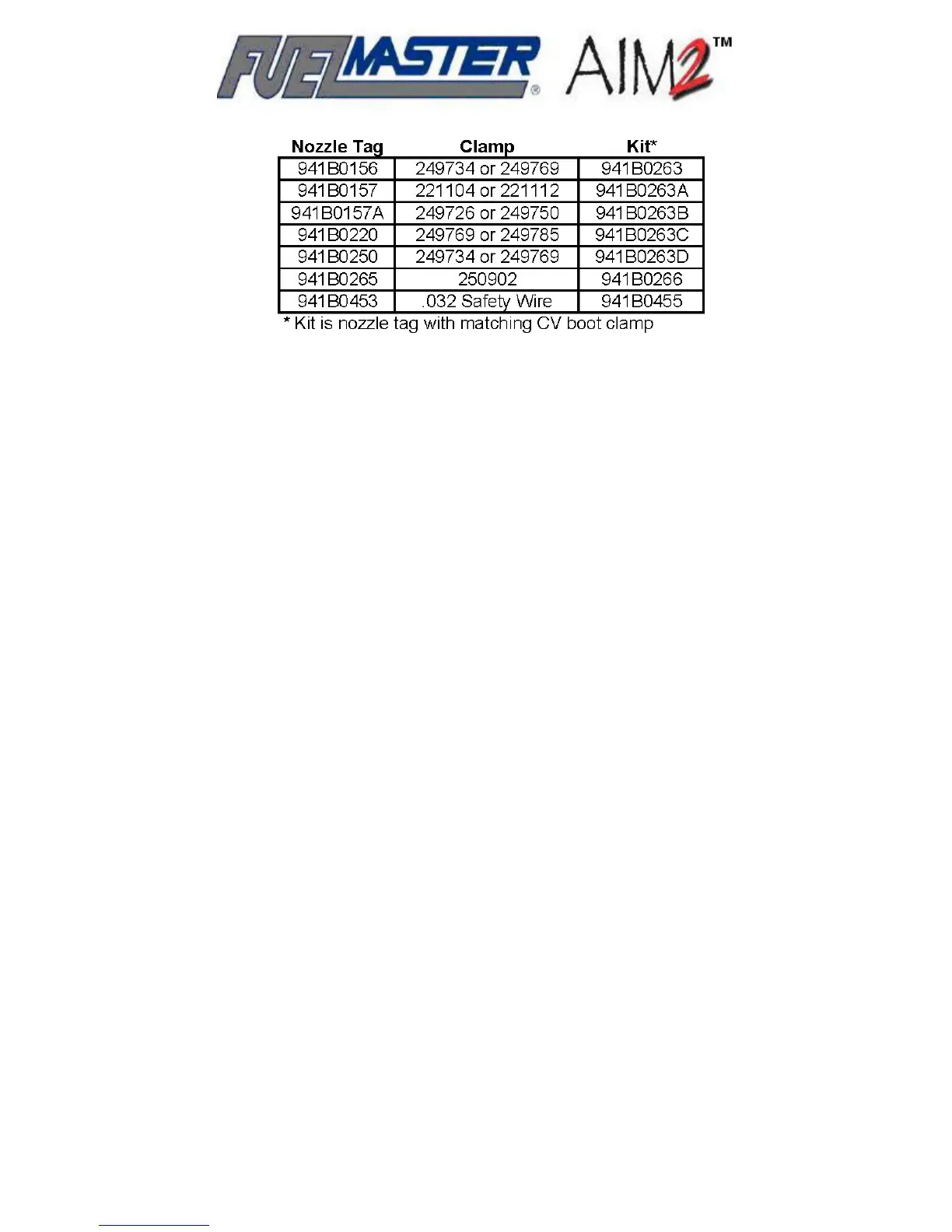
Table 2-3. Nozzle Tag Clamp and Kit Part Numbers
Filler Neck Rings/RFID Interface Module. Like the nozzle tags, filler neck rings contain
an antenna coil and RF/ID chip for communications with the nozzle tag. The filler neck ring has a
48 inch pigtail for connection to the RFID Interface Module (also referred to as Lump Board). Filler
neck rings are available in a variety of sizes for installation on a variety of vehicle fuel tank filler
necks (see Table 2-4 for a breakdown of sizes, profiles, and pigtail lengths). Filler neck rings may
be glued in place with a gasoline and oil-resistant adhesive such as Seal-All from Eclectic
Products, Permatex or 3M Super Weatherstrip adhesive, or Gorilla Glue (for rough surfaces). If
you cannot find one of these adhesives, try to find something with similar properties which is gas
and oil-resistant, and will not damage the rubber surface of the filler neck ring. Lipped filler neck
rings may also be tacked in place with screws if care is taken not to contact the internal coil of the
filler neck ring.
The RFID Interface Module generates the signal for the filler neck ring to communicate to the
nozzle tag. When the nozzle tag is brought close enough to the filler neck ring, information (hose
number) in the nozzle tag is received by the filler neck ring and transmitted through the RFID
Interface Module and RFID Extension Cable to the AIM2™ module. Early variations on the RFID
Interface Module had connectors exiting straight out of the end of the module. Current versions of
the module have connectors positioned at right angles to the module. There are also some newer
variations with clear (instead of black) potting. Figure 2-4 illustrates a sampling of the vehicle
components which complete the connections from the filler neck ring forward to the AIM2™
module.
Connecting Cables. The AIM2™ module receives connections from an assortment of cables
designed for the application. RFID Extension Cables connect between the RFID Interface Module
and AIM2™ module, and are available in 15, 20, 30, 50, and 80 foot lengths. Connections through
the OBD port provide information and power to the AIM2™ module. Figure 2-5 is of an OBD II light
duty connection cable with a pass-thru connector which allows for connection of an OBD
diagnostic tester without disconnecting AIM2™. Other cables are available for other types of OBD
connections.
Cables for analog connections to a speed sensor or chronometer have pigtails for the necessary
connections. Analog chronometer connections do not connect to vehicle power. AIM2™ module
power must be derived from an OBD or speed sensor cable connection.