28
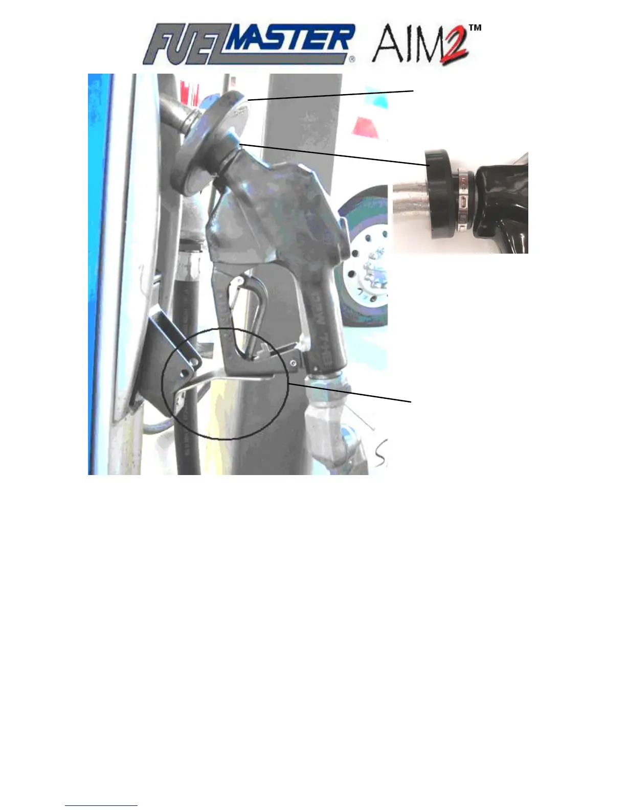
Nozzle Tag
(example, without
security clamp)
Security
Clamp
Installation
(example)
Nozzle
Hang-Up
Extension
(example)
Figure 3-2. Sample Nozzle Tag Installation
A list of vehicles is sent to Syn-Tech Systems when new passive fuel systems are purchased. Syn-
Tech reviews the list and selects the appropriate filler neck rings and connecting cables best suited
for the vehicles. For other requirements, refer to Table 2-4 to select the correct filler neck ring, and
Table 2-5 to select suitable connecting cables/devices.
Selecting the FMU Mounting Location
In addition to the need for dispenser control, a passive FMU-3500 also needs to be positioned where
it can communicate to all the vehicles being fueled through it. Communications to the vehicle is to the
AIM2™ module which is not usually mounted within direct sight of the FMU. The AIM2™ module is
often installed under the vehicle dash or in some kind of weatherproof compartment to protect it from
the elements.
When using the standard antennas provided with the FMU, the FMU-3500 should be mounted within
40-60 feet of the vehicle fueling positions. If traffic is continually moving between the fueling vehicles,
or if the FMU is inside a building or behind a wall, external antennas may be installed to restore the
line-of-sight.