FUJITSU DL3100
User’s Manual D-5
FUSE
Signal connect to +5V through 3.3KΩ resistance.
SLCTIN¯¯¯¯¯¯¯¯ (Valid for Epson ESC/P2 emulation only)
When the signal is low logic level, no DC3 control
code or DC1 control code is received.
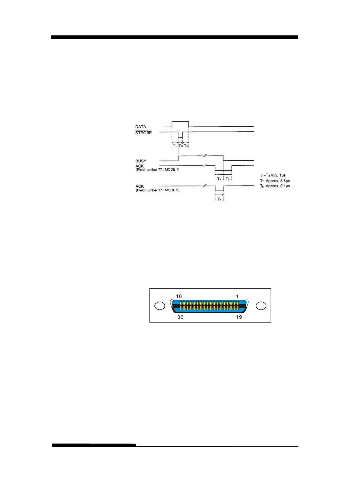
Clock and signal logic level
Signal logic level
Input: high logic level: 2 ~ 5V
low logic level: 0 ~ 0.8V
Output: high logic level: 2.4 ~ 5V
low logic level: 0 ~ 0.4V
Parallel interface connector diagram
Note:
1. Use a standard parallel interface cable to connect
the printer and the computer. The length should
not exceed 2 meters. Connect the 25P plug to the
computer, and connect the 36P plug to the printer.