28
ڀ ŪŲŃƗƒŃŷŤťůŨŃŲũŃŦŲűŷŨűŷŶ
,Q)$667HVW&+PRGHDIWHUOLQNLQJ56%
LQWHOHPHWU\2))PRGHOLQNWKHUHFHLYHU\RXZDQW
WHOHPHWU\WR7KHWUDQVPLWWHUZLOOVKRZWKHWHOHPHWU\RI
WKHODVWOLQNHGWUDQVPLWWHU
1
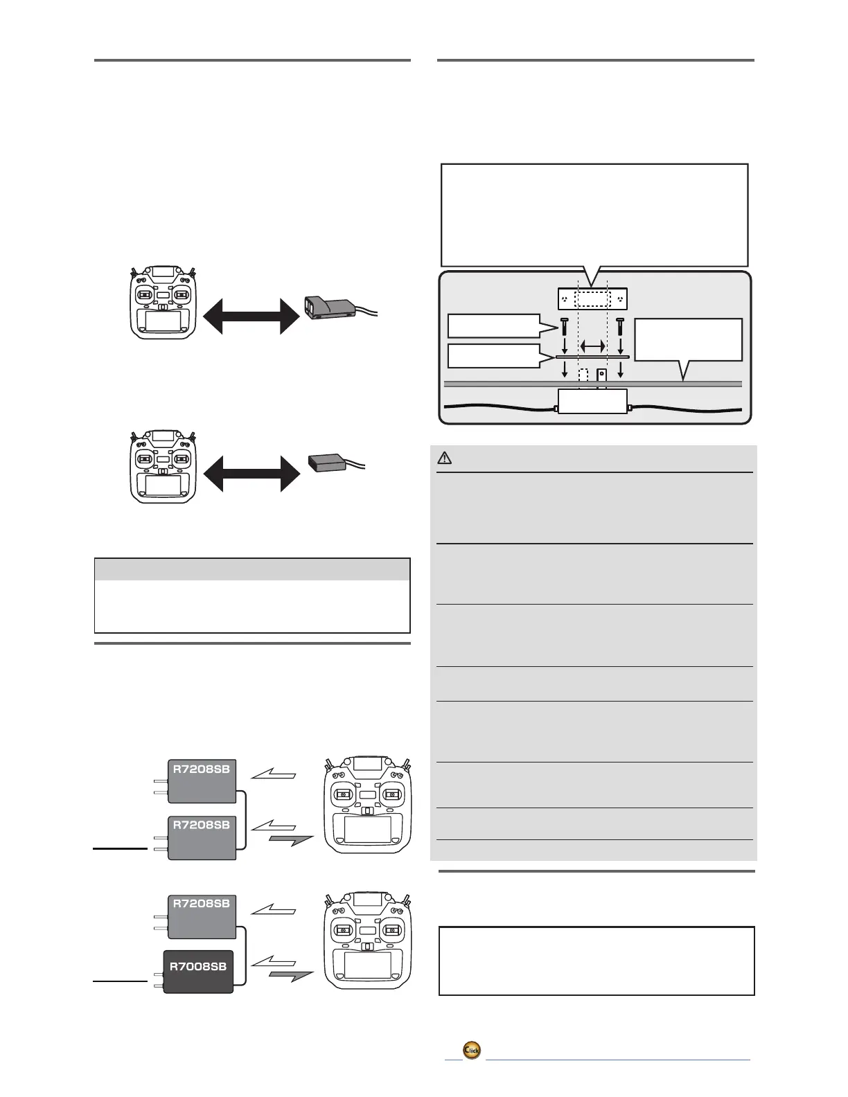
Installtworeceiversontheaircraftasshowninthe
connectionexample.
2
Linkthetworeceiversusingthedualreceiverfeature
ofthetransmitter.
Forsystemswithoutdualreceivercapability,link
eachreceiverinturn.
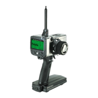
Transmitterinlinkmode
Transmitterinlinkmode
ForFASSTest26/18CHSelectdualmodeandlinkprimary
*Followthelinkprocedure
foreachreceivermanual.
ForFASSTest26/18CHSelect
dualmodeandlinksecondary
Turnonthemain
receiverandlink
Turnonthesub
receiverandlink
◆ Abouttelemetrysystem
Whenusingthedualreceiverfunction
・Thetelemetryfunctionofthemainreceivercanbeused
・Sub-receivertelemetryfunctionisnotavailable
HowtoDualRxLink
TelemetryforFASSTest12CH
TelemetryOFF
mode
Telemetry
Telemetry
TelemetryOFF
mode
FirstLink
FirstLink
Telemetrydisplayofsecond-linkedreceiver.
TelemetryOFFfirst-Linkedreceiver.
Display
Display
#1
SecondLink
#2
SecondLink
#2
#2
#1
#1
#2
#2
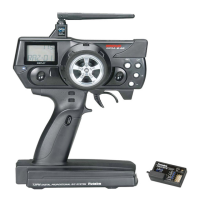
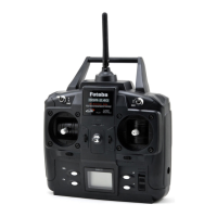
FASSTestreceiver
e.g.
ReceiverSwitchESW-1J
(6:-FRQQHFWVD)XWDEDUHFHLYHUWRDEDWWHU\DQGLV
turned on and off in an FET circuit. Compared to using a
PHFKDQLFDOVZLWFKLWDOORZVPRUHFXUUHQWWREHVHQWZLWK
less loss.
Whenthemodelisnotbeingused,alwaysremoveordisconnect
thebattery.
■ Whentheswitchisoff,aslightamountofcurrentstillflows.Unlessthe
switchandbatteryaredisconnected,thebatterywillbedamagedfrom
excessivedischarge.
Alwaysmakesurethattheswitchharnessisfirmlyattachedto
thefuselageofthemodel.
■ Thereisthedangeroflossofcontrolandcrashingiftheconnectoris
disconnectedbyvibrationandshock.
Donotchargethereceiverbatterythroughtheswitchharness.
Disconnectthereceiverbatteryandchargetothemanufactures
instructions.
■ Thereisnochargeconnectorinthisswitch.
Neverreversethebatterypolarity.
■ Reverseconnectionwillimmediatelydestroythereceiver,servo,etc.
Ensurethattheunitismountedinanareathatwilleliminateex-
posuretofuel,waterandvibration.
■ Aswithanyelectroniccomponents,properprecautionsareurgedto
prolongthelifeandincreasetheperformanceoftheESW-1J.
Allowaslightamountofslackinthecablesandfastenthemata
suitablelocationtopreventanydamagefromvibrationduring
flight.
NeversoldertheESW-1Jorattempttorepair,deform,modifyor
disassemblethem.
DonotusetheESW-1JwithanythingotherthananR/Cmodel.
Switch
< Attachment >
Lessthan5mmof
mountingplate
Attachedscrew
Switchcover
8VHWKHPRXQWLQJSODWHIURPWKHUHFHLYHURQRIIVZLWFKDVD
WHPSODWH IRUWKHFXWRXWDQG VFUHZ KROHV 0RXQW WKH VZLWFKRQWKH
VLGHRIWKHIXVHODJHRSSRVLWHWKHHQJLQHH[KDXVWDQGZKHUHLWZRQ¶W
EHLQDGYHUWHQWO\ WXUQHGRQRU RIIGXULQJKDQGOLQJRU VWRUDJH%H
FHUWDLQWKHVZLWFKPRYHVZLWKRXWUHVWULFWLRQDQG³VQDSV´IURP21
WR2))DQGWKDWWKHFXWRXWDOORZVIXOOPRWLRQRIWKHVZLWFKLQERWK
directions.
WARNING
Servo(Option)
3XUFKDVHVHUYRVDSSURSULDWHIRUWKHLULQWHQGHGXVH
*Analog servosPD\QRWEHXVHGZKHQRSHUDWLQJLQWKH
FASSTest 12CH mode.
When operating in the FASSTest12CH mode use digital
servosWKLVLQFOXGHVDOObrushless and S.BUS servos.
*InthecaseofFASSTest26CH,itispossibletolink
withthreereceivers.Inthatcase,select"Triple".