EasyManua.ls Logo

FutureLogic Gen2 Universal PSA-66-ST2RU - Evaluation Cable 14-pin Base Port Pin-outs; Evaluation Cable DB9 RS232 Port Pin-outs; GDS Adaptor Cable

FutureLogic Gen2 Universal PSA-66-ST2RU
37 pages
Print Icon
To Next Page IconTo Next Page
To Previous Page IconTo Previous Page
Loading...
Operators and Technicians Manual
2006 2013 FutureLogic, Incorporated. All Rights Reserved. MNL Page 16 04/29/2013
MNL-000032 REV.D
The following table lists the pin out of the 14 pin base port. The Modulated +24VDC pin has the same
function as the bezel port pin.
Table 5-7 Evaluation Cable 14 pin Base Port Pin-outs
Table 5-8 Evaluation Cable DB9 RS232 Port Pin-outs
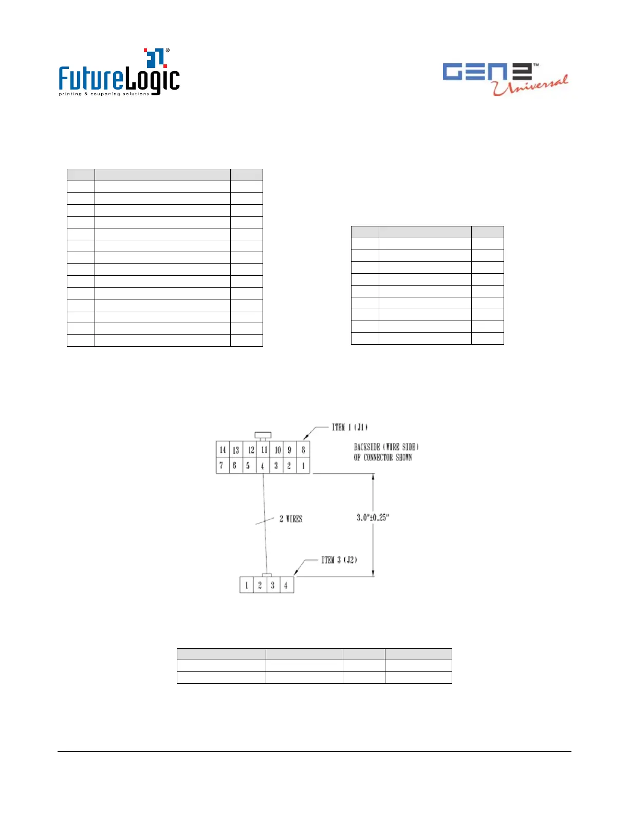
GDS Adaptor Cable
The GDS adaptor cable changes the RS232 14 pin down to a 1 x 4 Molex mini fit to match the GDS
power connector standard.
Figure 5-5 GDS Adaptor Cable
Table 5-9 GDS Adaptor Cable Connectors
From Connector
To Connector
Color
Length
J1-5
J2-3 *
Black
3.0” ±0.25”
J1-6
J2-4
Red
3.0” ±0.25”
* Use Grounding Terminal (Item 5) for J2-3.
GDS Adaptor Cable P/N
150
-00164-100
PIN
FUNCTION
I/O*
1
No connect
-
2
No connect
-
3
No connect
-
4
No connect
-
5
GND
-
6
+24 VDC
-
7
GND
-
8
No connect
-
9
Modulated +24VDC
O
10
GND
-
11
RS232 RXD
I
12
RS232 TXD
O
13
DTR
O
14
RTS
O
Pin
Function
I/O*
1
No connect
-
2
TX
O
3
RX
I
4
No connect
-
5
GND
-
6
DTR
O
7
No connect
-
8
RTS
O
9
No connect
-
*I/O viewed from the printer

Table of Contents

Related product manuals