The expansion DVI-Power
G&D DVIVision · 41
Installation guidelines
Installing the G&D Power Card into the computer
At first, install the G&D Power Card into the computer:
1. Take the manual of the computer and of the motherboard that is installed within
the computer.
2. Open the casing of the computer to gain access to the expansion slots.
3. Assemble the G&D Power Card of the expansion DVI-Power to a free expansion
slot of the computer.
Connecting the signal lines to the slot card
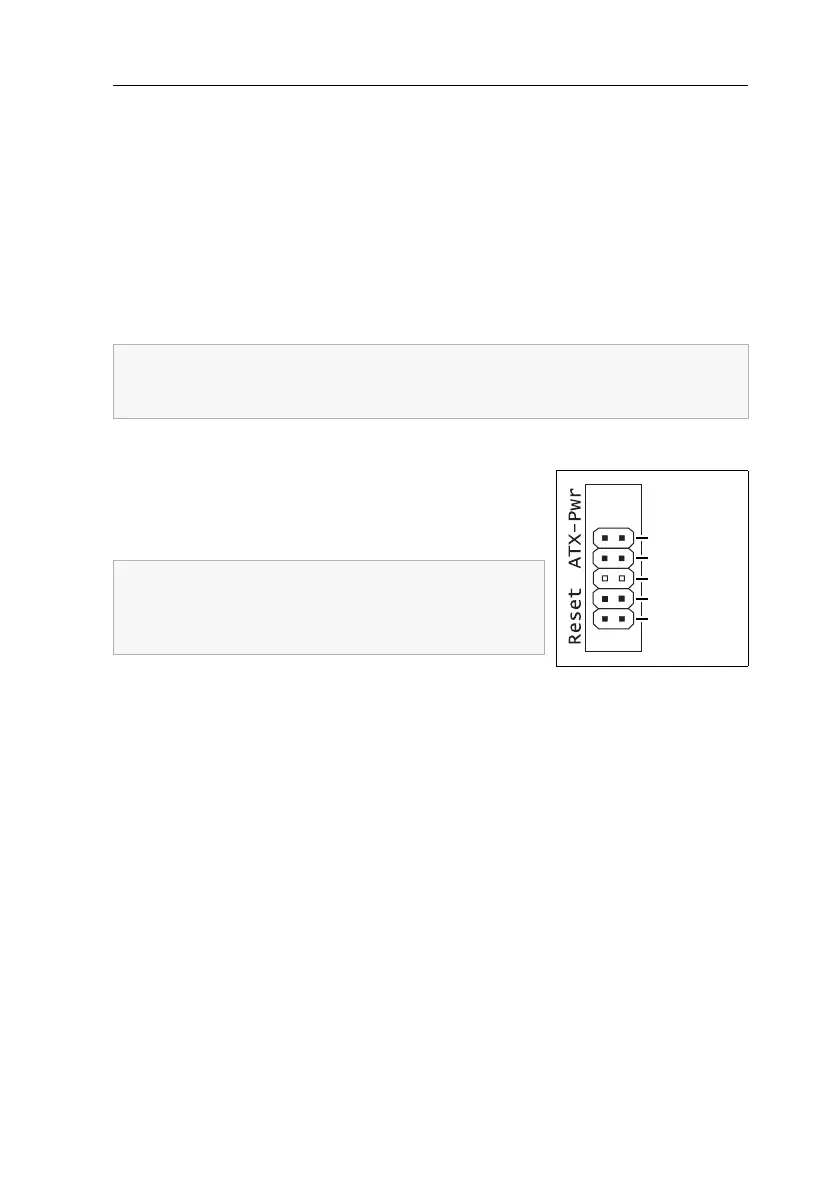
In the following, the signal lines ATX-Power and Reset of
the motherboard are connected to the pin bar of the
G&D Power Card (see figure). A further connection at
the computer casing guarantees the use of these buttons.
Pwr-Sw: Connect the ATX-Power button cable of the
computer casing to these pins. In case the connection cable is not long enough, it
can be extended with one of the extension cables.
Pwr-MB: Connect the pins you have written down before with the plug position of the
ATX-Power button on the motherboard. Use one of the supplied connection cables for
this purpose.
Res-Sw: Connect the Reset button cable of the computer casing to these pins. In case the
connection cable is not long enough, it can be extended with one of the extension cables.
Res-MB: Connect the pins you have written down before with the plug position of
the
Reset button on the motherboard. Use one of the the supplied connection cables
for this purpose.
The G&D Power Card requires no slot at the motherboard of the computer. The
installation only serves as assembly position for the ATX module at the back
panel of the computer.
Write down the plug positions of the cables, which are
leading from the ATX-Power button and the Reset but
-
ton of the casing to the motherboard. Afterwards, dis-
connect the cables.
Res-MB
Res-Sw
n. occupied
Pwr-MB
Pwr-Sw