Page 36
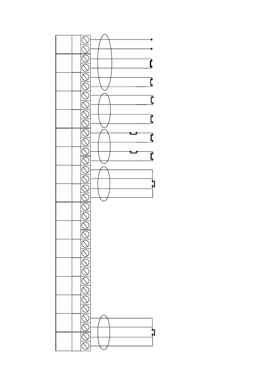
Fig. 22 Typical 4 Wire Configuration
+ -
12V
+ -
AZ1
+ -
TZ1
+ -
AZ2
+ -
TZ2
+ -
AZ3
+ -
TZ3
+ -
AZ4
+ -
TZ4
+ -
AZ5
+ -
TZ5
+ -
AZ6
+ -
TZ6
+ -
AZ7
+ -
TZ7
+ -
AZ8
+ -
TZ8
ALARM
ZONE 1
+ LOOP
TAMPER
ZONE 1
- LOOP
ALARM
ZONE 2
+ LOOP
TAMPER
ZONE 2
- LOOP
ALARM
ZONE 3
+ LOOP
TAMPER
ZONE 3
- LOOP
ALARM
ZONE 4
+ LOOP
TAMPER
ZONE 4
- LOOP
ALARM
ZONE 5
+ LOOP
TAMPER
ZONE 5
- LOOP
ALARM
ZONE 6
+ LOOP
TAMPER
ZONE 6
- LOOP
ALARM
ZONE 7
+ LOOP
TAMPER
ZONE 7
- LOOP
ALARM
ZONE 8
+ LOOP
TAMPER
ZONE 8
- LOOP
DETECTOR
SUPPLY
Single Passive Infra-Red
Normally Closed Alarm Pair
Normally Closed Tamper Pair
+ Supply
- Supply
Double Contact
x
erm
na
or
u
on
(if required)
Single Pressure Pad
Normally Closed Alarm Pair
Normally Open Push Button
Normally Closed Tamper Pair
Normally Closed Alarm Pair
Normally Open Device
Normally Closed Tamper Pair
Normally Closed Alarm Pair
Normally Closed Tamper Pair
Normally Closed Alarm Pair
Normally Closed Tamper Pair
Single Contact
Note:
If exit terminator is required program zone as ET
If unset doorbell is required allocate chime to the
ET zone.
Exit terminator zone must be AZ zone
Setting Mode should be programmed for ET
Note:
AZ zones are +ve
TZ zones are -ve
To comply with BS4737 alarm and tamper loops
should be oposite polarity
Any unused zones may be programmed to off
and the factory fitted link can be removed from the
zone terminals.
It is not advisable to connect normally open devices
onto a TZ loop
PR5892 Rev11 800 Series Eng Ref 15.qxd 16/11/2006 11:20 Page 36
 Loading...