Page 44
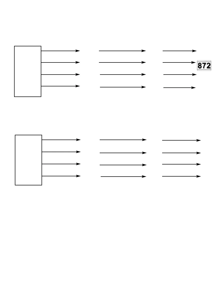
Fig. 30a GardTec 872 Zone Expanders (Group1) remote from panel (inc Cable
Colours) for EXP1 to EXP8
Blue
Yellow
Black
Red
Each of the Expander cards should be idented using the jumpers JP1-JP8 on the
card.
Fig. 30b GardTec 872 Zone Expanders (Group2) remote from panel (inc Cable
Colours) for EXP9 to EXP16
Blue
Yellow
(SAD2)
Black
Red
Each of the Expander cards should be idented using the jumpers JP1-JP8 on the card.
JP1= EXP9, JP2-EXP10, JP3=EXP11, JP4=EXP12, JP5=EXP13, JP6=EXP14,
JP7=EXP15, JP8=EXP16.
Note: In all above examples max cable run is 150 metres. It is recommended that
PSUs are used to supply the detectors on remote expanders
Note: Remote Expander Cable(s) Part No.01-094 will be required.
The expander cable plug MUST be plugged in to the main PCB EXP socket(s) with the
red wire to pin 1.
If required expander cards may be mounted in a remote expander box Part No 02-066
These expander boxes are ideal housings when the expander cards are to be mounted
away from the control panel.
Expander
Cable 1
Plug to
EXP1
LH Molex
Connector
Main PCB
Pin 1
872 Expander
Card(1)
SCLK
SAD1
0V
12V
872 Expander
Card(2)
SCLK
SAD1
0V
12V
Expander
Cable 2
Plug to
EXP2
RH Molex
Connector
Main PCB
Pin 1
872 Expander
Card(10)
SCLK
SAD1
0V
12V
872 Expander
Card(9)
SCLK
SAD1
0V
12V
PR5892 Rev11 800 Series Eng Ref 15.qxd 16/11/2006 11:20 Page 44
 Loading...