83
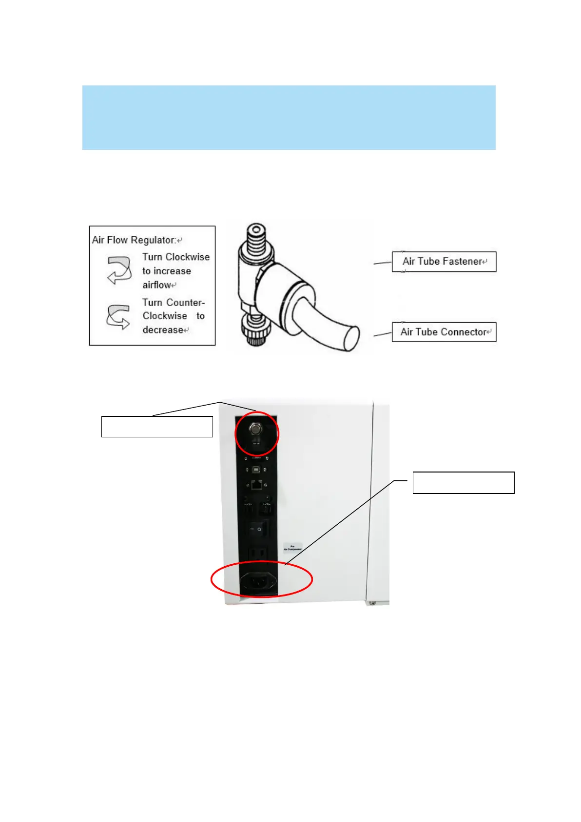
3) Connect a ¼ " tubing to the air tube fastener valve on the air compressor.
NOTE
It is important that the ¼ " air tubing has clean, straight cuts on each end. Jagged or
slanted cuts will not produce adequate sealing capabilities.
4) Take the unattached end of the ¼ " air tubing (other end already connected to air compressor) and
connect it to the air tube connector on the air assist valve. Make sure you press down on the air tube
fastener when inserting the ¼ " air tubing, to form a tight, secure attachment as indicated in the
diagram below.
5) Both the Air-Assist
Valve and AC Power Sockets are located on the rear side of laser system.
6) Plug the air compressor’s power cord A into the AC internal power socket.
7) Plug the female end of power cord B to the AC power socket on laser system and the male end to an
external power outlet.
Congratulations, you have finished setting up the air compressor. Make sure you have the proper
SmartAIR nozzle installed (depending on your application), before you turn on and utilize the air
compressor.