Standard applications
5.12 QS4 Technical Reference Manual
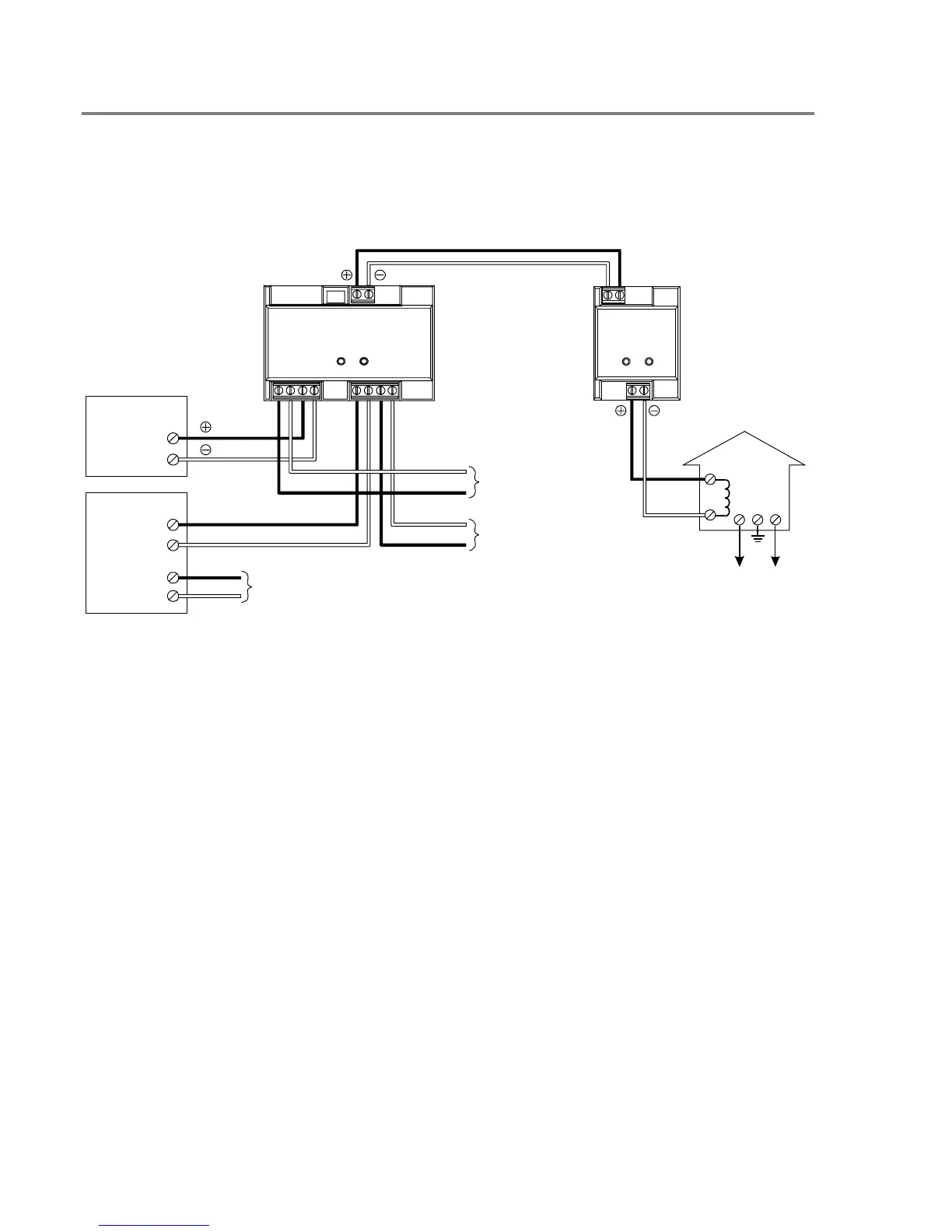
Auxiliary protective signaling
Wire as shown in Figure 5-6. Program the SIGA–CC1 as a common alarm output device. Plus and
minus symbols indicate signal polarity with the circuit turned on.
Municipal circuit
Master box
12
12
2–CTMSIGA–CC1
10 9
12435687
LOOP B+
LOOP B–
LOOP A+
LOOP A–
TO DATA OUT TERMINALS
ON LAST DEVICE (CLASS A ONLY)
SLIC
TO DATA IN TERMINALS
ON NEXT DEVICE
24VDC+
24VDC–
LISTED 24VDC
SUPPLY
TO NEXT DEVICE
Figure 5-6: Auxiliary protective signaling cabling diagram
Technical Manuals Online! - http://www.tech-man.com