Standard applications
5.8 QS4 Technical Reference Manual
Coded alarm signaling
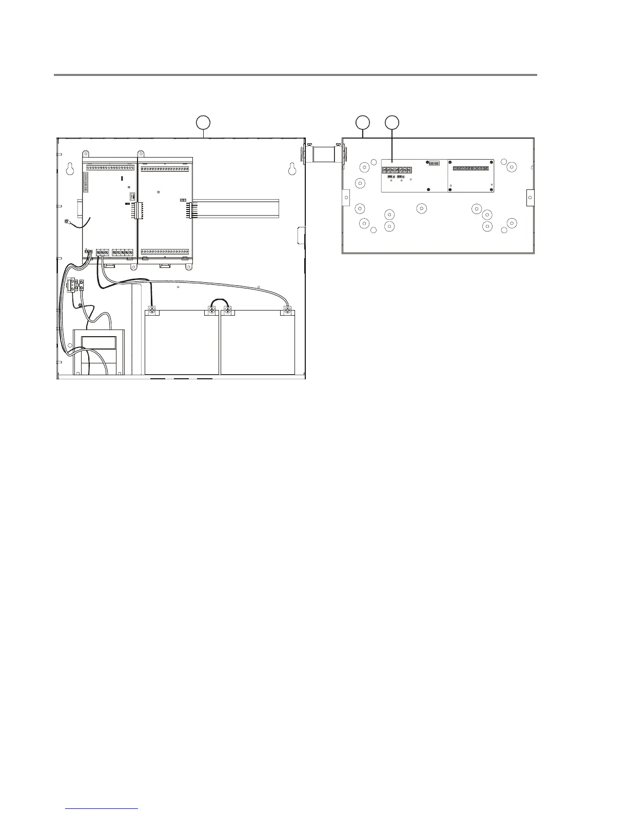
1 2 3
1. FACP: Fire alarm control panel with a CPU,
PS6, ZB16–4, and standby batteries.
2. MFC–A Accessory Enclosure: Used for
mounting the remote fire alarm equipment.
3. CDR–3 Bell Coder: Provides coded alarm
signals for 24 Vdc notification appliance circuits
and one of three evacuation signals (temporal, 60
bpm, and 90 bpm).
Note: CDR–3 must have firmware version greater
than 2.0.
Notes
• Place the MFC–A and the FACP in the same
room and connect using a section of conduit no
greater than 20 ft in length. Run all wiring
between cabinets through the conduit.
• Set SW–6 on CDR–3 to ON. Refer to the CDR–
3 installation sheet for programming
information.
• Install a 10 kΩ EOLR across TB2–1 and TB2–
2, and TB2–11 and TB2–12 on the CDR–3.
• Set JP2 on the PS6 for ACC PWR
• If the system uses a NAC circuit on an SLIC to
output the coded signal, program the NAC
circuit signal rate as Steady.
• If the system uses the NAC 1 circuit on an SLIC
to output the coded signal to audible notification
appliances, set JP1 and JP2 on the SLIC to
EXT.
Figure 5-1: Typical equipment layout, coded alarm signaling application
Technical Manuals Online! - http://www.tech-man.com