Installation
2.14 QS4 Technical Reference Manual
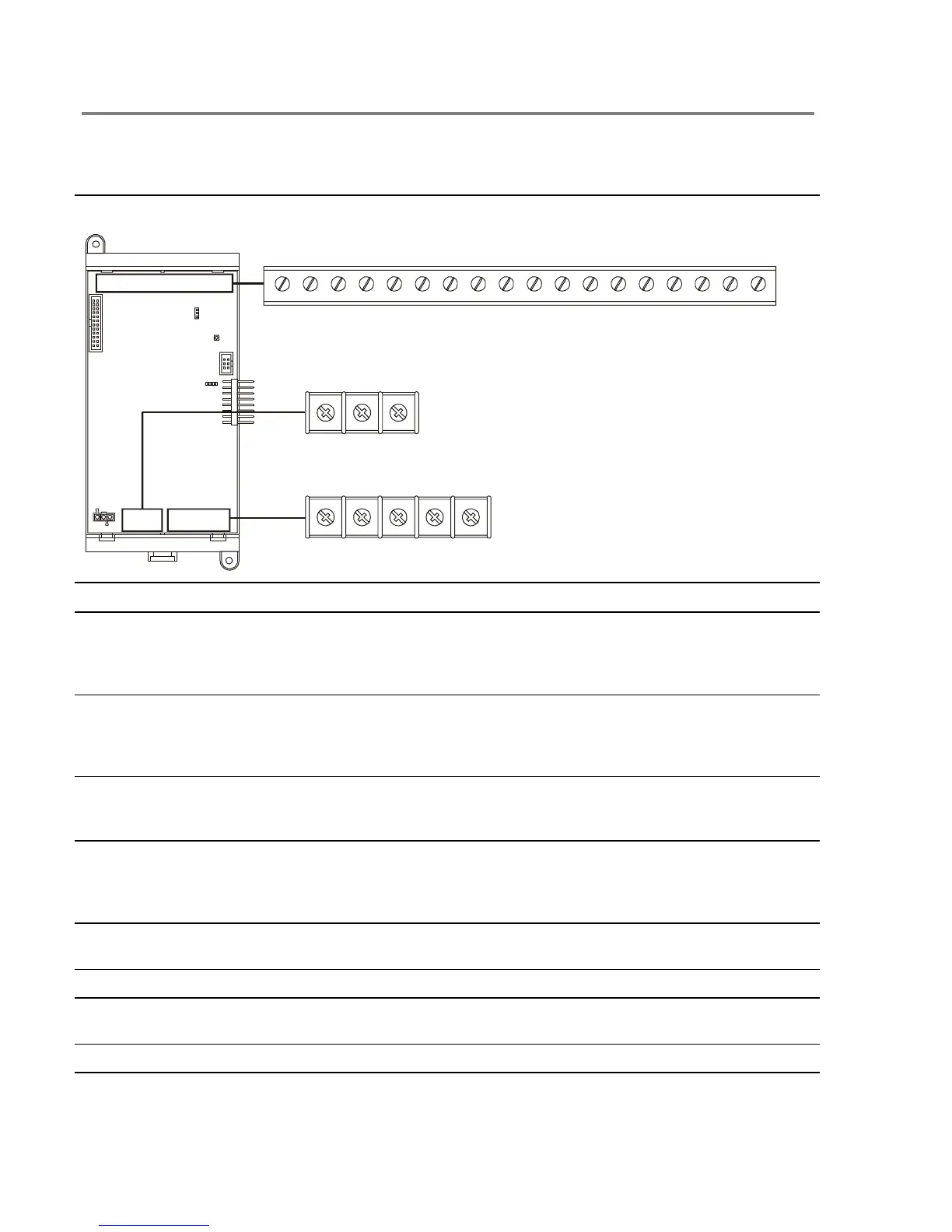
Terminal definitions
Table 2-1: PS6 Power Supply card terminal definitions
SMOKE
ACC PWRRELAY 1 RELAY 2 RELAY 3 RELAY 4 RS485 RS232
AUX POWER
AUX1 AUX2 COM AUX3 COM
TB3
15432
NO C NC C NO C NO C NO N.C. RTS TX RX COM
–
+
–
+
BATT PWR
NC
TB2
1
3
2
–
+
TB1
1 18171615141312111098765432
Terminal No. Name Description
TB1–1, –2 Relay 1 NO, C Normally-open relay contacts that close automatically when
the panel processes an alarm event. The contacts remain
closed until all active alarm points restore and the panel
resets.
TB1–2, –3 Relay 1 C, NC Normally-closed relay contacts that open automatically when
the panel processes an alarm event. The contacts remain
open until all active alarm points restore and the panel
resets.
TB1–4, –5 Relay 2 C, NO
Normally-open relay contacts that close automatically when
the panel processes a supervisory event. The contacts
remain closed until the active supervisory point restores.
TB1–6, –7 Relay 3 C, NO Normally-open relay contacts that close automatically when
the panel energizes. The contacts open when the panel
processes a trouble event or when the panel loses power
and remain open until the trouble condition restores.
TB1–8, –9 Relay 4 C, NO Normally-open relay contacts that close depending on how
the user programs the panel.
TB1–10 N.C. Not used
TB1–11, –12 SMK/ACC PWR +, –
Provides regulated 24 Vdc for four-wire smoke detectors or
accessory devices depending on jumper setting.
TB1–13, –14 RS485 +, – Connects to the Channel 1 input on a remote annunciator
Technical Manuals Online! - http://www.tech-man.com