Installation
2.22 QS4 Technical Reference Manual
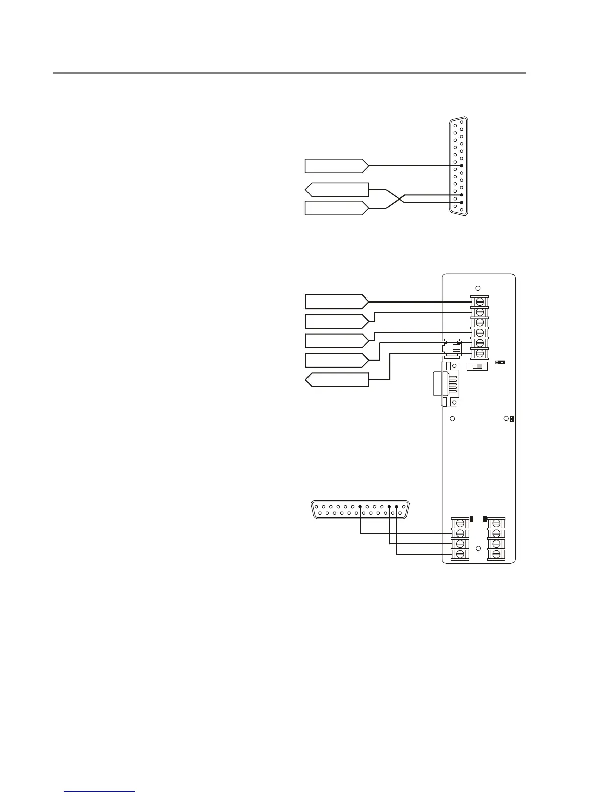
Connecting a PT–1S printer
For control panels with only a printer
1. Locate the printer in the same room as and
within 20 ft of the panel (printer wiring is
nonsupervised and power-limited).
2. Wire the printer cable to the RS232
connections on the power supply card then
plug the cable into the printer.
3. Set the printer switches for 9600 bps, 8 bits,
no parity. Refer to the documentation
included with the printer for more details.
PS6 TB1–16
PS6 TB1–18
PS6 TB1–17
DB–25P
REAR VIEW
2
TO
PT–1S
3
7
COM–COM
TX–RX
RX–TX
For control panels with a printer and a CDR–
3 Bell Coder module
1. Install the IOP3A in the same enclosure as
the CDR–3. Refer to appendix B.
2. Wire the IOP3A to the CDR–3.
3. Wire the printer cable to the RS232
connections on the IOP3A then plug the
cable into the printer.
4. Configure the IOP3A as follows:
JP1 = 2–3
JP2 = ON
JP3 = ON
JP4 = ON
SW1 = UP
5. Set the printer switches for 9600 bps, 8 bits,
no parity. Refer to the documentation
included with the printer for more details.
DB–25P
REAR VIEW
TO
PT–1S
COM–COM
TB1
1
2
3
4
5
6
3
2
1
J
B
1
J
B
4
S
W
1
U
P
J
B
2
J
B
3
1
2
3
4
TB3
TB2
CDR–3 TB2–4
CDR–3 TB2–5
CDR–3 TB2–6
CDR–3 TB2–7
PS6 TB1–17
IOP3A
732
RxD–TxD
TxD–RxD
Technical Manuals Online! - http://www.tech-man.com