Installation
QS4 Technical Reference Manual 2.21
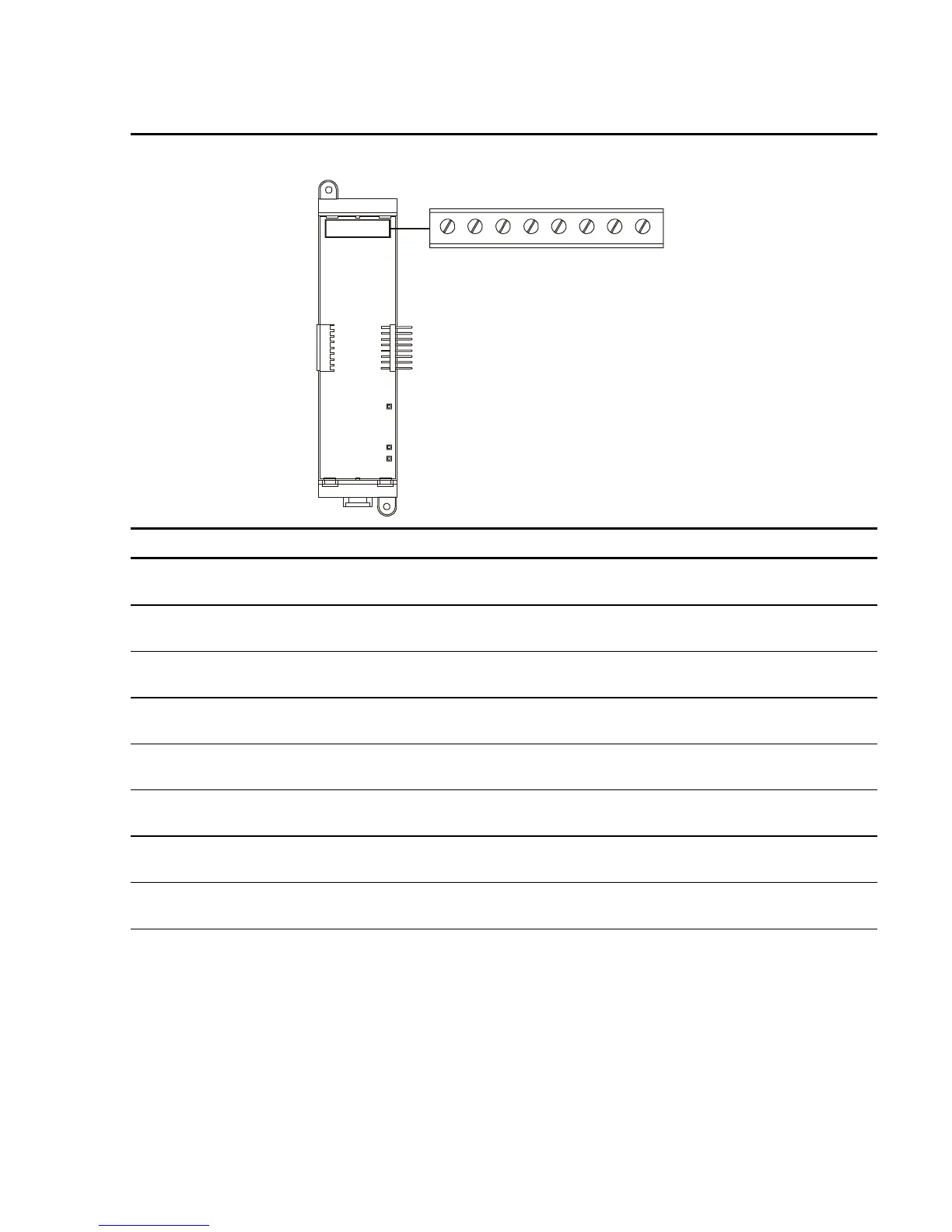
Table 2-7: DLD Dual Line Dialer card terminal definitions
TIP RING TIP RING TIP RING TIP RING
IN OUT IN OUT
LINE 1 LINE 2
5876
TB1
1432
Terminal No. Name Description
TB1–1 LINE 1 TIP IN Connects to the Tip In connector on the telco side of an RJ31X
block via an RJ–12 modular cable.
TB1–2 LINE 1 RING IN Connects to the Ring In connector on the telco side of an
RJ31X block via an RJ–12 modular cable.
TB1–3 LINE 1 TIP OUT Connects to the Tip Out connector on the protected premises
side of an RJ31X block via an RJ–12 modular cable.
TB1–4 LINE 1 RING OUT Connects to the Ring Out connector on the protected premises
of an RJ31X block via an RJ–12 modular cable.
TB1–5 LINE 2 TIP IN
Connects to the Tip In connector on the telco side of an RJ31X
block via an RJ–12 modular cable.
TB1–6 LINE 2 RING IN
Connects to the Ring In connector on the telco side of an
RJ31X block via an RJ–12 modular cable.
TB1–7 LINE 2 TIP OUT
Connects to the Tip Out connector on the protected premises
side of an RJ31X block via an RJ–12 modular cable.
TB1–8 LINE 2 RING OUT Connects to the Ring Out connector on the protected premises
of an RJ31X block via an RJ–12 modular cable.
Technical Manuals Online! - http://www.tech-man.com