System calculations
QS4 Technical Reference Manual A.9
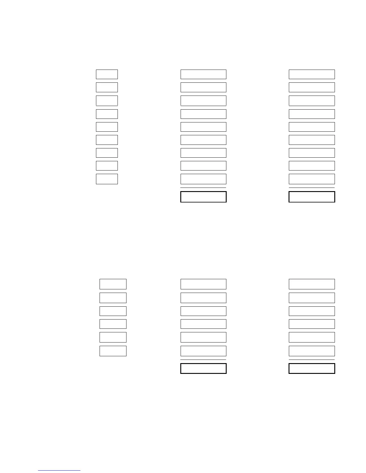
(A) Base panel current load calculation
Card Qty
Standby
Current (mA)
Qty ×
××
× Standby
Current (mA)
Alarm
Current (mA)
Qty ×
××
× Alarm
Current (mA)
PS6 1 82 82 100 100
CPU/Display 117 135
SL30 (–1)
[1]
11
SLIC 33 57
DLD 13 20
ZB16–4 117 152
ZA8–2 73 116
X485 60 60
ZR8
[2]
11 18
Totals
[3]
Notes
[1] Add 0.75 mA for each energized LED.
[2] Add 18 mA for each energized relay.
[3] Base panel current must be less than 1.32 mA.
(B) Smoke/Accessory (SMK/ACC) Power current load calculation (max 250 mA)
Card Qty
Standby
Current (mA)
Qty ×
××
× Standby
Current (mA)
Alarm
Current (mA)
Qty ×
××
× Alarm
Current (mA)
CPU/Display
[3]
117 123
SL30 (–1)
[1]
11
CDR–3 60 100
IOP3A 60 60
RPM
[2]
20 20
SIGA-UM, -MAB
[4]
21717
Totals
Notes
[1] Add 0.75 mA for each energized LED.
[2] Add 0.7 mA for each output used.
[3] This value includes RAI currents
[4] This represents the smoke power requirements. Only the
SIGA–UM or SIGA–MAB that signaled the alarm draws
alarm current. The remaining SIGA–UMs or SIGA–MABs
do not.
Technical Manuals Online! - http://www.tech-man.com
 Loading...