Product description
QS4 Technical Reference Manual 1.7
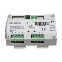
ZB16–4 Class B Conventional Zone Card circuits
1. IDC Circuits Z1 – Z12
Wiring configuration: Class B
Detector voltage: 20.33 – 24.76 Vdc, max ripple 2000 mV
Short circuit current: 75.9 mA, max.
Resistance: 50 Ω, max.
Capacitance: 100 µF, max
Wire size: 18 to 12 AWG (0.75 to 2.5 mm
2
)
End of line resistor: 4.7 kΩ, 1/2W
Supervised and power-limited
2. NAC Circuits Z13 – Z16
Wiring configuration: Class B
Output voltage: 24 Vdc, nominal
Output current: 2.0 A @ 24 Vdc
Wire size: 18 to 12 AWG (0.75 to 2.5 mm
2
)
End of line resistor: 10 kΩ, 1/2W
Supervised and power-limited
IDC specifications apply when programmed as IDC circuit
3. R1
Voltage: 24 Vdc, nominal
Wire size: 18 to 12 AWG (0.75 to 2.5 mm
2
)
4. R2
Voltage: 24 Vdc, nominal
Wire size: 18 to 12 AWG (0.75 to 2.5 mm
2
)
1
3
4
2
1
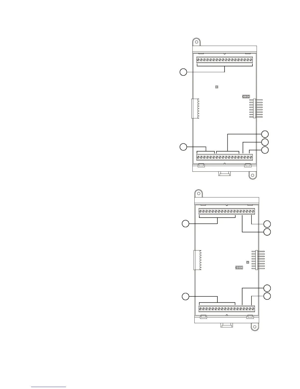
ZA8–2 Class A Conventional Zone Card circuits
1. IDC Circuits Zone 1 – Zone 3, Zone 5 – Zone 7
Wiring configuration: Class A
Detector voltage: 19.90 – 22.46 Vdc, max ripple 2000 mV
Short circuit current: 75.9 mA, max.
Resistance: 50 Ω, max.
Capacitance: 100 µF, max
Wire size: 18 to 12 AWG (0.75 to 2.5 mm
2
)
End of line resistor: 4.7 kΩ, 1/2W
Supervised and power-limited
2. NAC Circuits Zone 4, Zone 8
Wiring configuration: Class A
Output voltage: 24 Vdc, nominal
Output current: 2.0 A, 24 Vdc
Wire size: 18 to 12 AWG (0.75 to 2.5 mm
2
)
End of line resistor: 10 kΩ, 1/2W
Supervised and power-limited
IDC specifications apply when programmed as IDC circuit
3. NAC PWR IN (Zone 4)
Voltage: 24 Vdc, nominal
Wire size: 18 to 12 AWG (0.75 to 2.5 mm
2
)
4. NAC PWR IN (Zone 8)
Voltage: 24 Vdc, nominal
Wire size: 18 to 12 AWG (0.75 to 2.5 mm
2
)
1
2
3
1
4
2
Technical Manuals Online! - http://www.tech-man.com