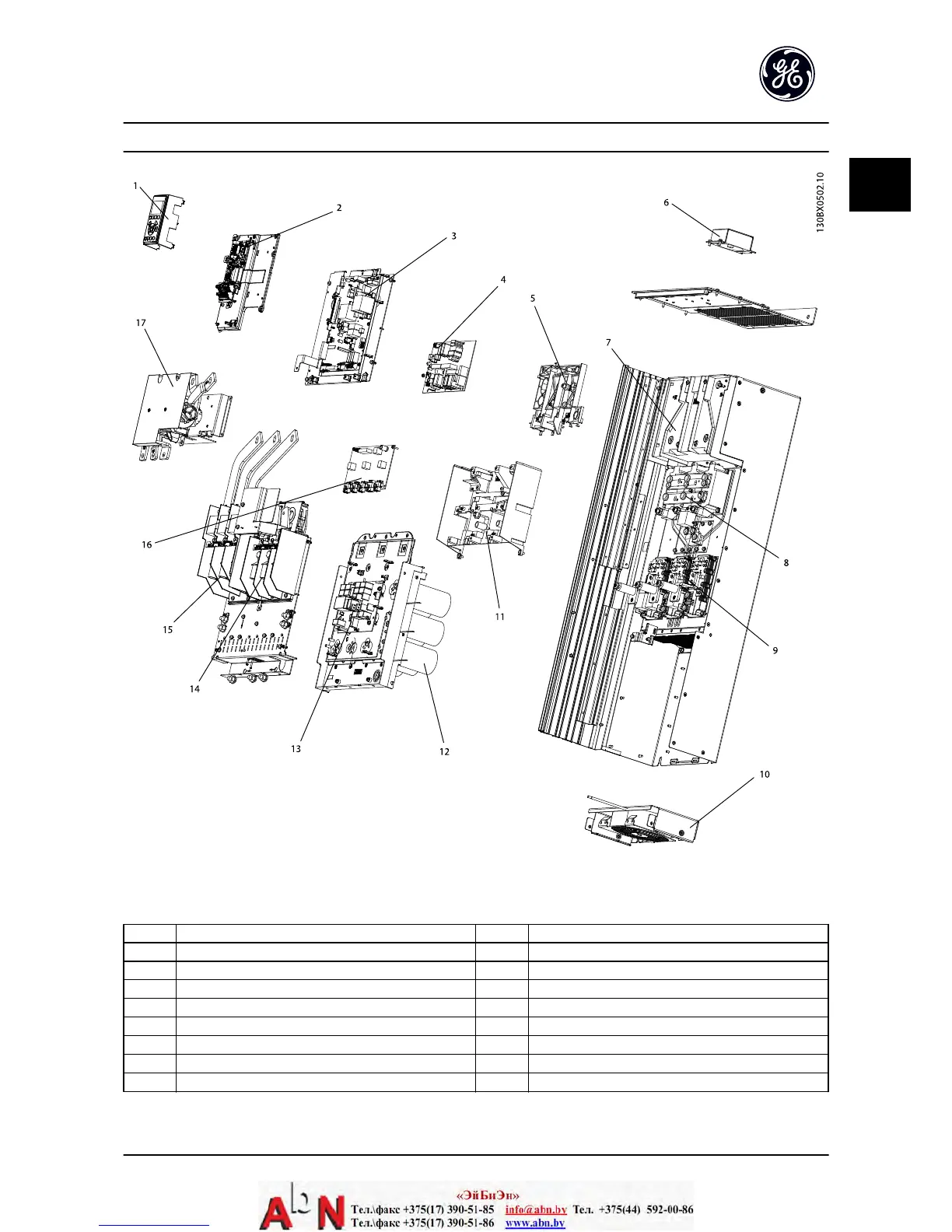
Figure 1.3 Exploded View Unit Sizes 41h, 42h, 43h, 44h
1 Local control panel mounting bracket 10 Heatsink fan
2 Control card and mounting plate 11 Gate drive support bracket
3 Power card and mounting plate 12 Capacitor bank
4 Inrush card 13 Balance/High frequency card
5 Inrush card mounting bracket 14 Motor output terminals
6 Top fan (IP20 only) 15 Line power input terminals
7 DC inductor 16 Gate drive card
8 SCR/Diode modules 17 (optional) RFI filter
9 IGBT modules
Table 1.3
Introduction AF-600 FP Design and Installation Guide
DET-768A 1-3
1 1

 Loading...


