22 GE INFORMATION D20MX HARDWARE USER’S MANUAL
CHAPTER 1: BEFORE YOU START
Power supply
The chassis-mounted power supply modules are switch-mode converters that provide
output power for the D20MX processor board, VME cards, modems and D20 Peripheral I/O
modules, as required. A redundant power supply can be installed to provide fail-over
protection to ensure continuous power to the D20.
If you have an extended system with more than five peripherals, the chassis-mounted D20
power supply is not adequate. In this case, you need to install an external power supply.
Table 7 lists the standard power supplies that are available. Other power supplies are
available for specific requirements. Contact GE Digital Energy for details.
Table 7: Available power supplies
Ensure your D20 power input is externally protected for over-current; otherwise damage to
the D20MX may occur. The required fuse rating depends on the power consumption of
your system.
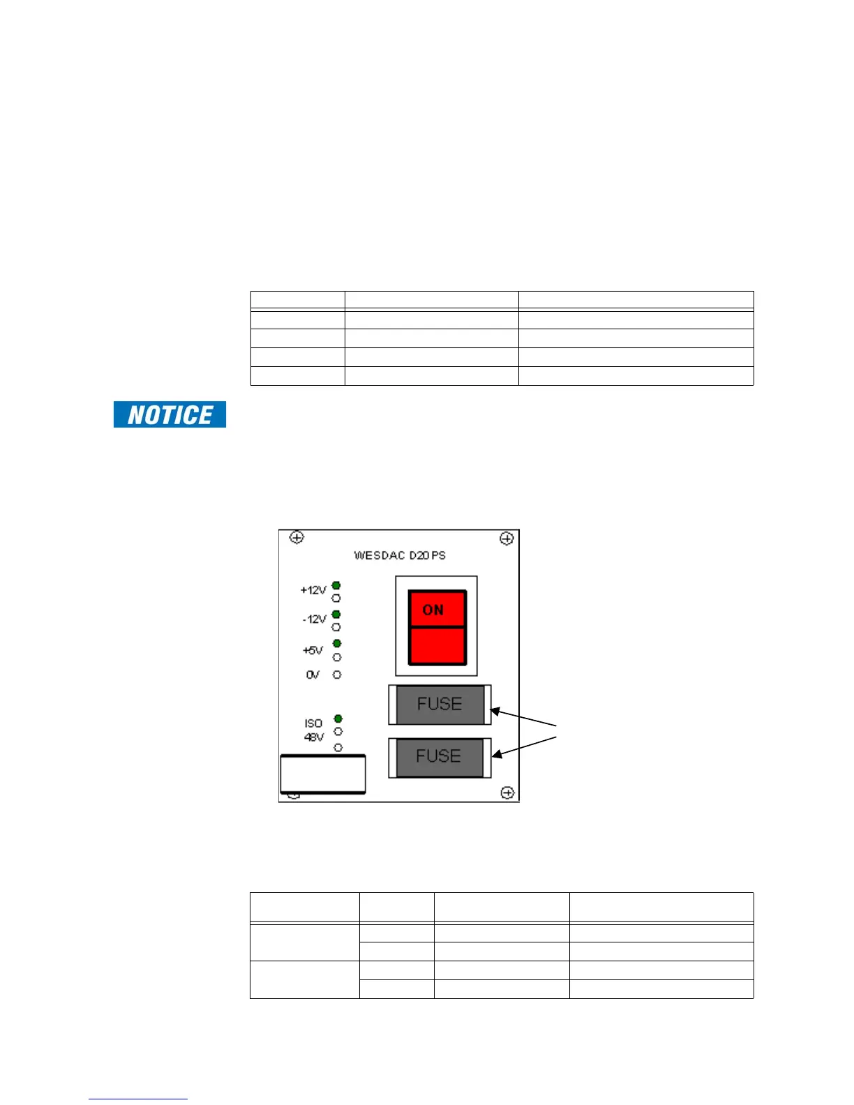
The D20 available power supplies, listed in Table 7 are equipped with two field replaceable
fuses.; see Figure 5.
Figure 5: D20 - Location of field-replaceable fuses
Field-replaceable fuses for the standard chassis-mounted Power Supplies are listed in
Table 8. These are the standard factory-installed fuses, unless otherwise specified. Always
replace with the same type and values of fuse.
Table 8: Field-replaceable fuses
GE part number Input Output
580-2004 20 to 60 V DC +5 V, 7 A; +12 V, 2 A; -12 V, 1 A; 24 V DC, 3 A
580-2005 20 to 60 V DC +5 V, 7 A; +12 V, 2 A; -12 V, 1 A; 48 V DC, 1.5 A
580-2006 100 to 300 V DC or 85 to 264 V AC +5 V, 7 A; +12 V, 2 A; -12 V, 1 A; 24 V DC, 3 A
580-2007 100 to 300 V DC or 85 to 264 V AC +5 V, 7 A; +12 V, 2 A; -12 V, 1 A; 48 V DC, 1.5 A
Power Supply Fuse Fuse Function Replacement Fuse
(¼inch by 1 ¼ inch Time Delay)
580 - 2004 F1 +DC Input 12 A / 250 V
F2 -DC Input 12 A / 250 V
580 - 2005 F1 +DC Input 12 A / 250 V
F2 -DC Input 12 A / 250 V