D20MX HARDWARE USER’S MANUAL GE INFORMATION 41
D20MX Processor
Chapter 3: Connecting to Devices
and Networks
Connect ing to Devic es and Networks
This chapter provides guidelines for making physical connections between the D20 and
substation and network devices.
Cabling overview
All physical connections are made to the connectors on the rear backplane of the D20
chassis or to the front on the D20MX processor module.
D20MX front panel connectors
The D20MX front panel can have one of the following layouts:
• Ethernet connectors (RJ45); see Figure 14.
• Front access Fiber optic connectors (ST); see Figure 15.
• Rear access Fiber optic connectors (ST) on a fiber optic daughter card; see Figure 16.
For a description of the operational status LEDs and port status LEDs, see “Front panel
LEDs ” on page 85.
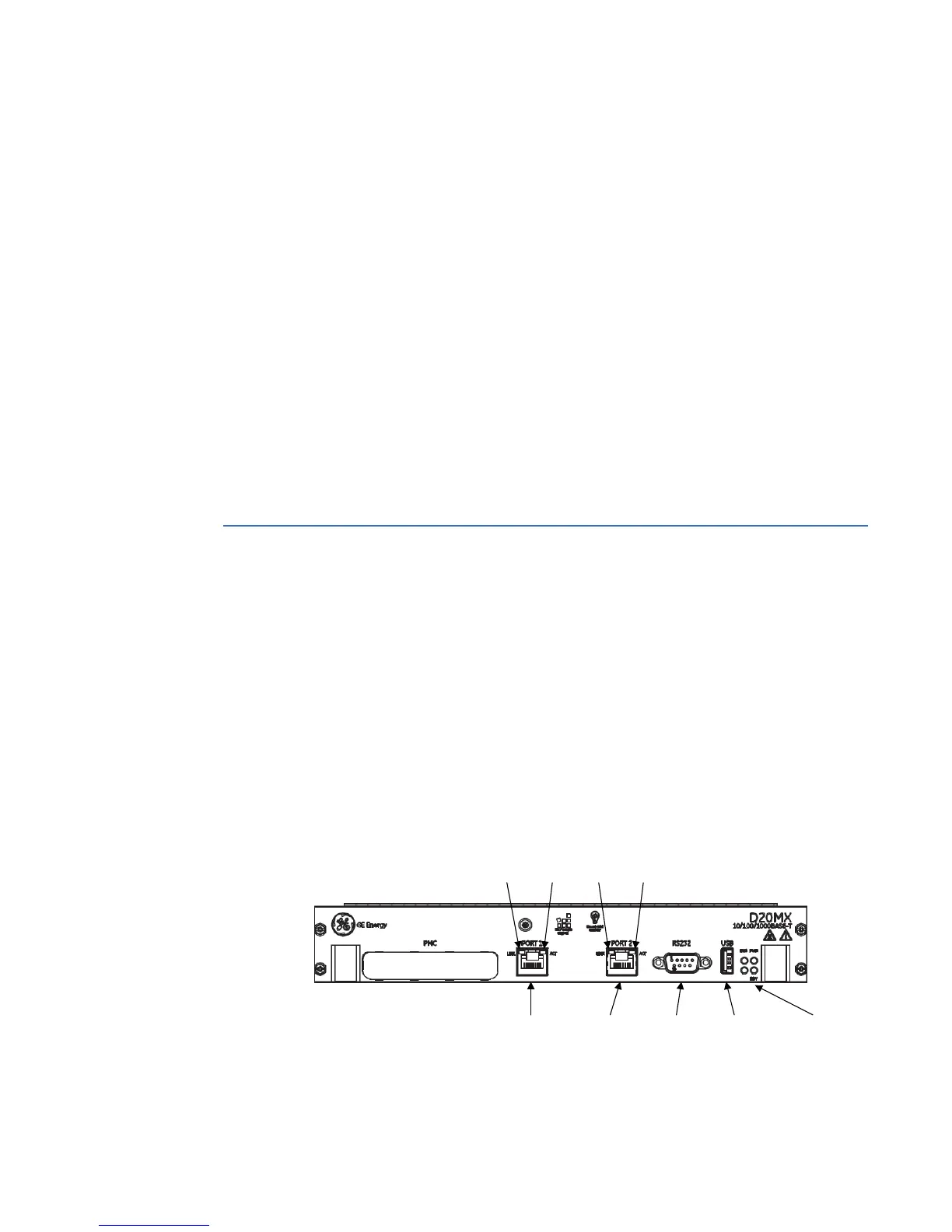
Figure 14: D20MX front panel with Ethernet connectors
Ethernet
Port 1
Ethernet
Port 2
RS232
Serial Port
Operational
Status LEDs
USB Port (not
supported)
Port 1
Status LEDs
Port 2
Status LEDs