42 GE INFORMATION D20MX HARDWARE USER’S MANUAL
CHAPTER 3: CONNECTING TO DEVICES AND NETWORKS
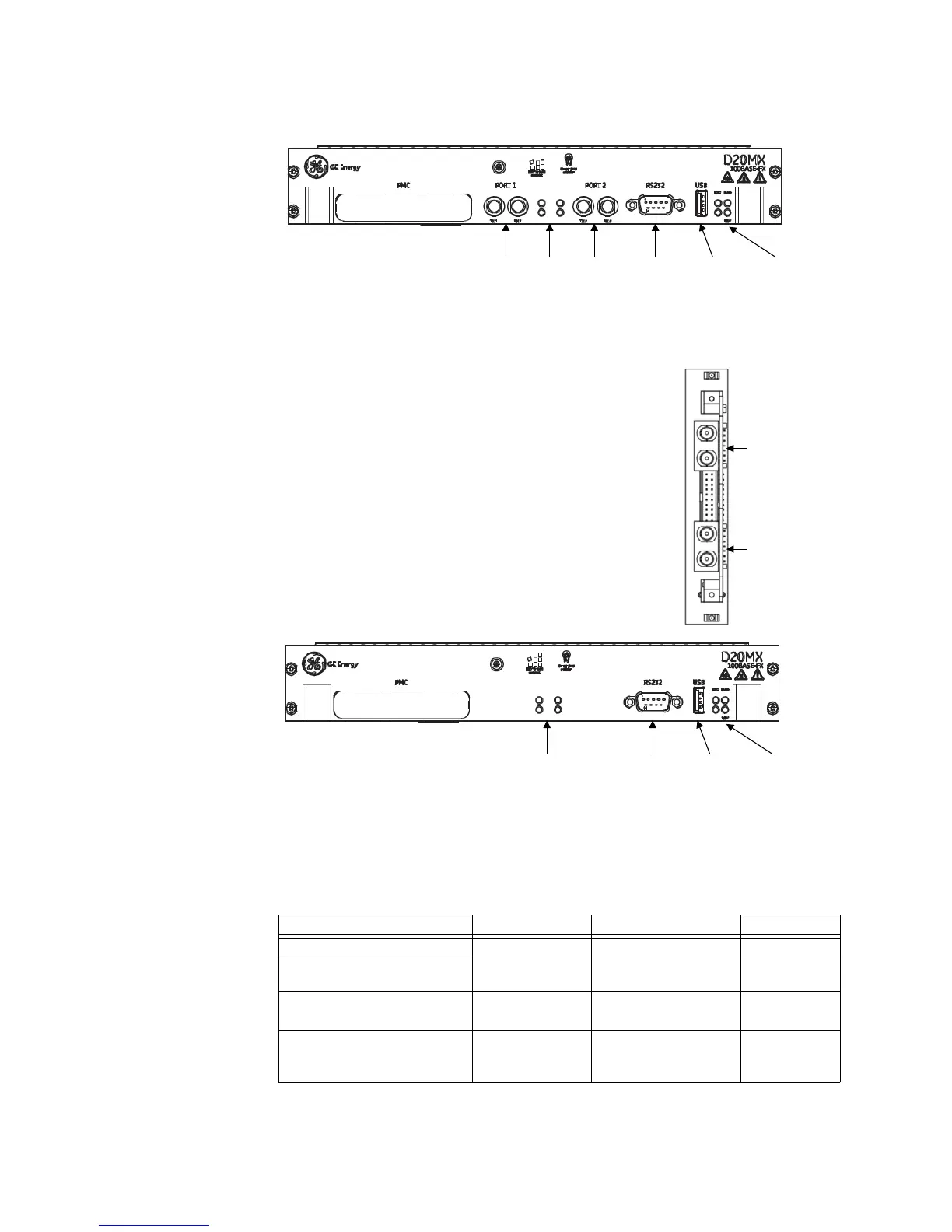
Figure 15: D20MX front panel with front access fiber optic connectors
Figure 16: D20MX front panel and fiber optic card with rear access fiber optic
connectors
General cabling requirements
Table 14 lists the cables required to connect to the D20MX:
Table 14: Connection cables
Fiber
Optic
Port 1
Fiber
Optic
Port 2
RS232
Serial Port
Operational
Status LEDs
USB Port
(not
supported)
Port
Status
LEDs
Fiber
Optic
Port 2
Fiber
Optic
Port 1
RS232
Serial Port
Operational
Status LEDs
USB Port
(not
supported)
Fiber Optic
Port Status
LEDs
Fiber Optic card,
D20 chassis back view
D20MX front panel
Media Designation Cabling Connector
Serial
RS-232 Shielded DB-9 female
D.20 Link RS-485
2 wire
Shielded DB-9 female
Twisted Pair Ethernet
(GE part number 526-3001 only)
10/100/1000BASE-T UTP (Unshielded Twisted
Pair) – CAT 5 or better
RJ-45
Fiber optic
(GE part number 526-3003 and
526-3005LF only)
100BASE-FX 1300 nm, 50/125 μm and
62.5/125 μm multimode
duplex fiber cable
ST-style
connectors