CHAPTER 2: INSTALLING THE D20MX
D20MX HARDWARE USER’S MANUAL GE INFORMATION 37
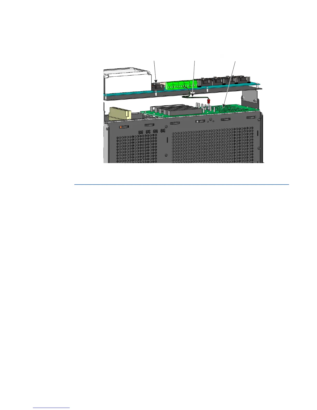
Figure 12: 0 V cable connection
Required tools and materials
Before beginning the installation procedures, have the following tools and equipment
available:
• Appropriate device cables for D.20 connections (GE part number 977-0089)
• For D20MX Non-VME with Dual 10/100/1000Base-TX (part number 526-3001): CAT5
network cables for RJ-45 Ethernet connections (GE part number 977-0280 or
equivalent)
• For D20MX Non-VME with Dual 100Base-FX (part number 526-3003) and D20MX Non-
VME with Dual 100Base-FX Fiber Optic Card (part number 526-3005): multi-mode
duplex fiber cable - ST connectors.
• Flathead screwdriver with 0.6 mm by 3.5 mm blade (for terminal block wiring)
• #1 Phillips screwdriver (for panel or DIN rail mounting the unit)
• #2 Phillips screwdriver (for rack mounting the unit)
• Needle-nose pliers
• Wire cutters
• Wire strippers
• Approved network settings for the device
• Windows-based PC with any Windows-based terminal emulation software and Web
browser software installed
• 12 AWG wire (minimum) for protective earth
• 2 ring connectors, Panduit part number PV10-14R for 12 AWG [3.3 mm²] wire for
protective earth terminal
WESTERM D20M+ SS
Termination Panel
D20 VME Chassis
WESTERM D20VME -
VME Bus Backplane
0 V
Cable