38 GE INFORMATION D20MX HARDWARE USER’S MANUAL
CHAPTER 2: INSTALLING THE D20MX
Grounding the D20MX
Surge and noise suppression components used on the D20MX are designed to prevent
nuisance operation and damage to internal components. To ensure correct protective
operation, the earth ground wire (14AWG green wire) on the D20 chassis must be
connected to a low impedance ground rail of a secondary cabinet or rack.
When making ground connections, ensure that all surfaces that are used for grounding
are free of dirt, residue and corrosion.
Do not power up the D20 before establishing a proper protective earth connection.
Unpacking the D20MX
Carefully remove the D20MX from its packaging. Visually inspect the unit to ensure it has
not sustained any visible damage during transit. If there are visible signs of damage, report
it immediately to the carrier.
Package contents
The following items are provided as part of your D20MX shipment:
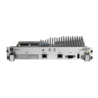
• D20MX unit (GE part number 526-3001, or 526-3003, or 526-3005)
• For 526-3005LF only:
– D20MX to Fiber Card Harness (975-1236)
– D20MX 100BASE-FX Rear LC FO Card (part number 526-3103LF) or D20MX
100BASE-FX Rear ST FO Card (part number 526-3104LF)
• Lower filler plate (part number 953-1015)
• Blank plate for D20MX install (part number 953-1014)
•0 V wire cable (part number 975-1237)
• For 526-3005LF installed in 500-0280 only:
– Termination Panel, D20MX extended mounting (952-2087)
• GE Digital Energy Product Documentation CD (GE part number 581-0002)
• GE Digital Energy D20MX Documentation CD (GE part number 588-0075 V120)
Verify that you have received all items. GE parts include a unique number, typically in the
format XXX-XXXX, that can be used as a reference.
Connecting the power supply
The D20MX processor board is supplied power through the WESTERM D20M+ SS
backplane. Power connections to the backplane are made on connector block TB1.
For the WESTERM D20M+ SS and WESTERM D20M+ (see Figure 13, “WESTERM D20M+SS:
power supply connections”) the power supply connections:
• 1 and 2 are used for input power connections based on the D20 power supply
• 4 and 5 can be used as a switched auxiliary power supply source

 Loading...