CHAPTER 3: CONNECTING TO DEVICES AND NETWORKS
D20MX HARDWARE USER’S MANUAL GE INFORMATION 51
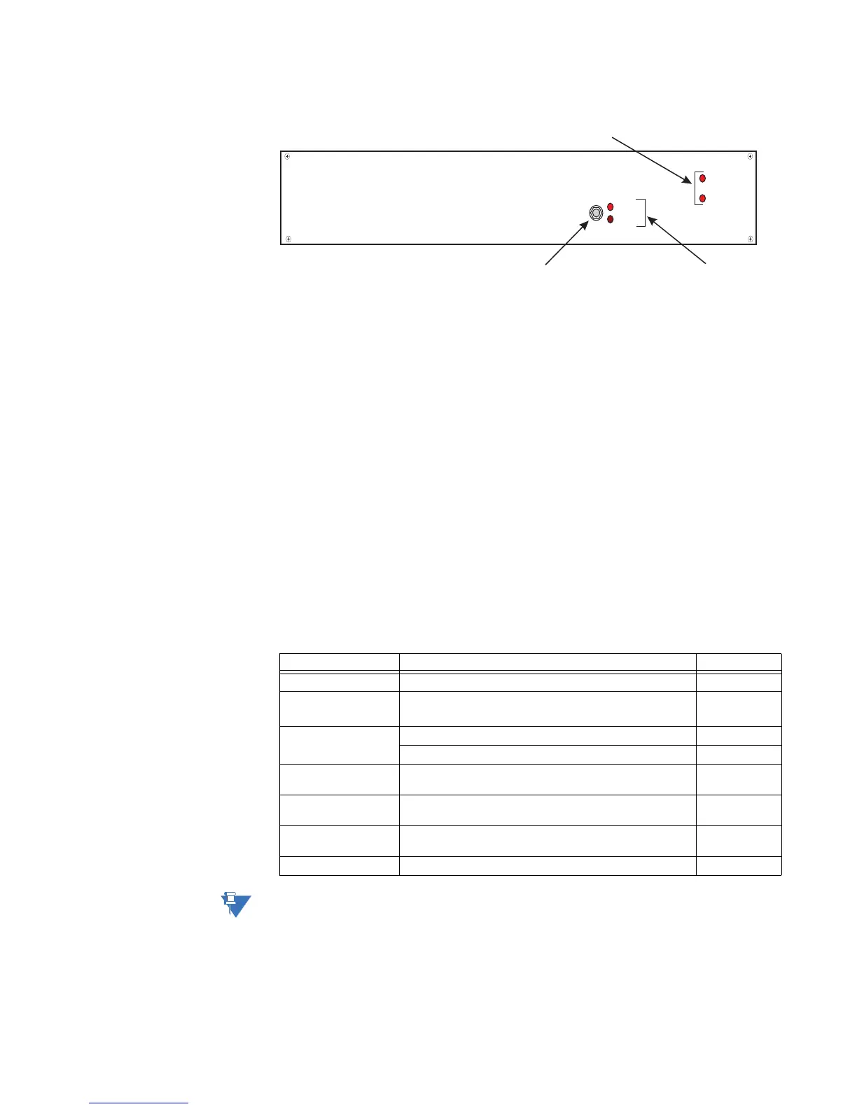
Figure 21: RS-232 Switch panel
A pair of LEDs marked CCU A and CCU B indicate which of the D20 units is currently active.
If the hardware or software of the active unit fails, it is automatically switched offline and
serial connections to the field are transferred to the standby unit. A toggle switch on the
RS-232 switch panel can be used to switch the D20 devices between active and standby
modes.
Failover sequence
If the active D20 unit fails, the following actions occur:
1. The standby D20 unit detects the failure through the lack of a heartbeat signal on the
ping cable or through a status change on the watchdog cable.
2. The standby D20 unit attempts to pull the RS-232 switch panel to assume the active
state.
3. The RS-232 switch panel transfers all serial field connections to the standby D20,
which then becomes the active D20.
Required components
To implement a redundant D20 system, you need the components: listed in Table 21.
Table 21: Redundant D20 system - required components
Pins 4 on switch panel connectors J2 through J9 are tied together and to the panel’s power
supply. Any loading from field devices on these pins will load the RS-232 panel power
supply and should be taken into consideration when sizing power supplies.
Ac tiv e/Standby Sw itc h
Power Indicator LEDs
CCU Indicator LEDs
CCU A
CCU B
PWR A
PWR B
Component Function Part Number
RS-232 Switch Panel Communications switch. 517-0247
Power Supply Power supply to power the RS-232 switch panel.
Input: 85 – 264 V AC or 90 – 350 V DC.
580-0046
Watchdog Cable
Assembly
Connects D20 A to the RS-232 switch panel. 977-0160
Connects D20 B to the RS-232 switch panel. 977-0160
Ping Cable Assembly Links both D20 units to facilitate a heartbeat message
that determines the status of the active unit.
977-0122
RS-232 Serial Cable Connects the D20 to the RS-232 switch panel which is
then connected to external field devices.
977-0121
Power/SysFail Cable Connects the RS-232 switch panel to D20 external power
supply.
970-0161
Ground Cable Provides a ground connection for the RS-232 switch panel. 970-0182