50 GE INFORMATION D20MX HARDWARE USER’S MANUAL
CHAPTER 3: CONNECTING TO DEVICES AND NETWORKS
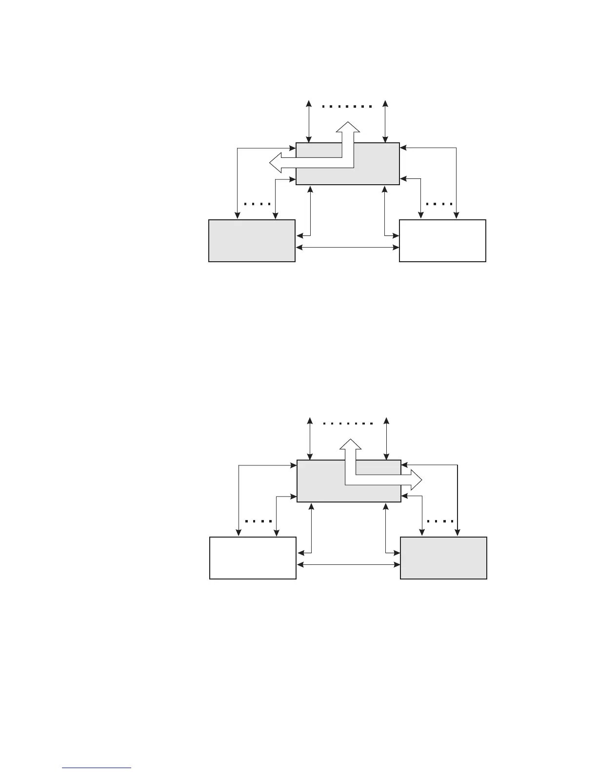
Figure 19: Redundant D20 system with CCU A active
If the Active CCU fails:
• The Standby CCU detects the failure through the inter-CCU communications link.
• The Standby CCU commands the RS-232 Switch Panel to switch over all serial
connections.
• The RS-232 Switch Panel switches all serial field connections to the Standby CCU,
which now becomes the Active CCU.
If CCU A fails, CCU B becomes active. See Figure 20, “Redundant D20 system - If CCU A
fails”.
Figure 20: Redundant D20 system - If CCU A fails
RS-232 Switch Panel
CCU A
(Active)
CCU B
(Standby)
CCU B Serial
Communications
CCU A Serial
Communications
To Field Equipment
Inter-CCU
Communications
RS-232 Switch
Monitor and Control
RS-232 Switch Panel
CCU A
(Failed)
CCU B
(Active)
CCU B Serial
Communications
CCU A Serial
Communications
To Field Equipment
Inter-CCU
Communications
RS-232 Switch
Monitor and Control