34 GE INFORMATION D20MX HARDWARE USER’S MANUAL
CHAPTER 2: INSTALLING THE D20MX
7.3. Connect the 20-pin header end of the cable (part number 975-1236) to
connector P1 on the fiber optic daughter card.
7.4. Secure the cable to the fiber optic daughter card with a cable tie.
7.5. Insert the fiber optic daughter card partially into the chassis, and feed the other
ends of the cable through the middle slot in the chassis wall between the VME
slots and the peripheral slots.
7.6. Connect the other end of the cable (with two connectors) to the D20MX
connectors J3 (shorter length of cable) and J4 (longer length of cable).
See Figure 11, “Cable to fiber optic daughter card,” on page 36.
Ensure that the cable is not pinched.
7.7. Push the front panel of the fiber optic daughter card until it is fully inserted.
7.8. Tighten the front panel retaining screws to 3.5 in-lbs to secure the fiber optic
daughter card to the chassis.
8. Install the new lower filler plate (part number 953-1015).
9. Install the new filler plate (part number 953-1014) in the space above the D20MX.
10. Attach any required communication cables to the connectors on the front panel of the
D20MX or the backplane of the D20 chassis.
11. If the D20MX is being installed in a VME chassis, connect the 0 V cable (part number
975-1237):
11.1. Connect the bare end of the cable wire to the O V connector on the WESTERM
terminal block TB2-9.
11.2. Remove the wire from the lower 0 V connector on the VME backplane and
connect this wire to the male end of the 0 V cable.
11.3. Connect the female end of the 0 V cable to the lower 0 V connector on the VME
backplane.
See Figure 12, “0 V cable connection”.
12. Install the ferrite clamp.
If you ordered a complete D20 system including the D20MX with power cable, notice
that a ferrite clamp has already been attached to the power cable. Go to step 13.
If you ordered a D20MX upgrade kit or a D20 system without power cable, a ferrite
clamp included in the package is to be attached to the power inlet cable:
12.1. Ensure that you are sufficiently grounded to prevent ESD damage to the
D20MX or other components. See “Grounding the D20MX” on page 38..
12.2. Remove ferrite clamp (GE part number 460-0073) from the package; handle
with care as the magnetic material is fragile.
12.3. Pass the power cable through the channel, approximately 15 cm (6 inches)
from the connector on the chassis.
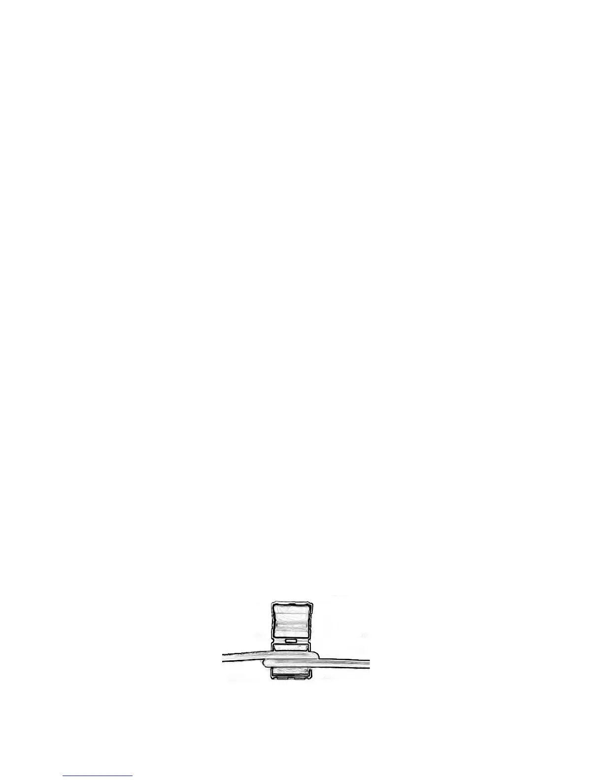
12.4. Loop the power cable one more time around and through the core. See
Figure 9.
Figure 9: Open ferrite clamp