Programming Site Data 1-21
March 2008
Calibration Factor 14.Enter a value for the flow Calibration Factor and press [ENT]. The
default value is 1.00, but values between 0.50 and 2.00 may be
entered.
15.The menu now varies, depending on whether you have activated
the TransFlection or Transit-Time mode.
• If you activated the TransFlection mode, the program asks for the
Depth of Reflector. This setting determines where in the pipe the
DF868 looks for the reflected signal. The default value is 50%.
Use the numeric keys to enter a value, and press
[ENT].
Note: The factory recommends activating the Reynolds Correction
Factor when the Depth of Reflector is set at 50%. You can
disable the Reynolds Correction Factor when the Depth of
Reflector is set at any other value.
• If you activated the Transit-Time mode, two steps appear.
a. Use the
[F1]-[F4] keys to select the desired Number of
Traverses, the number of times the ultrasonic signal traverses
the pipe, from 1 to 5.
b. The Transducer Spacing prompt displays the spacing of the
transducers, as calculated from the information you have
entered. Record this number and use it to properly space
transducers.
Note: If necessary, you can overwrite the spacing shown (using the
numeric keys) to match the actual physical spacing of the
transducers. The factory does not recommend overwriting the
spacing. If you must, do not change the spacing by more than
±10% from the value shown.
You have completed entering pipe parameters for clamp-on
transducers. Press
[ENT] to return to the start of the PIPE submenu, and
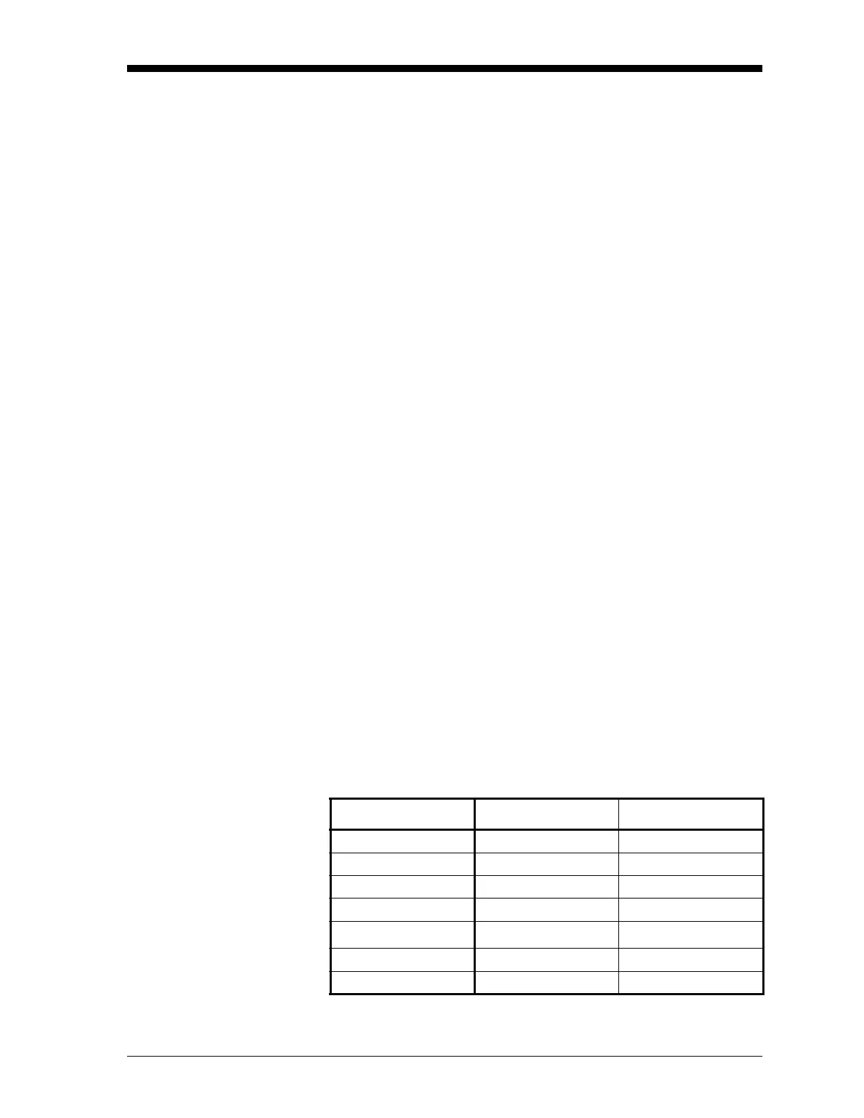
[EXIT] to leave the submenu. Table 1-11 below lists the numeric
parameters in the
PIPE submenu, with their high and low limits.
Table 1-11: Low and High Limits for PIPE Parameters
Parameter Low Limit High Limit
Wedge Angle 25° 90°
Pipe OD 0.12 in. 300 in.
Pipe Wall 0 in. 4.0 in.
Lining Thickness 0 in. 4.0 in.
Kinematic Viscosity 0.1
10,000 (E-6 ft
2
/s)
Path Length 0.12 in. 480 in.
Axial Length 0.12 in. 480 in.