5-198 F60 Feeder Protection System GE Multilin
5.6 GROUPED ELEMENTS 5 SETTINGS
5
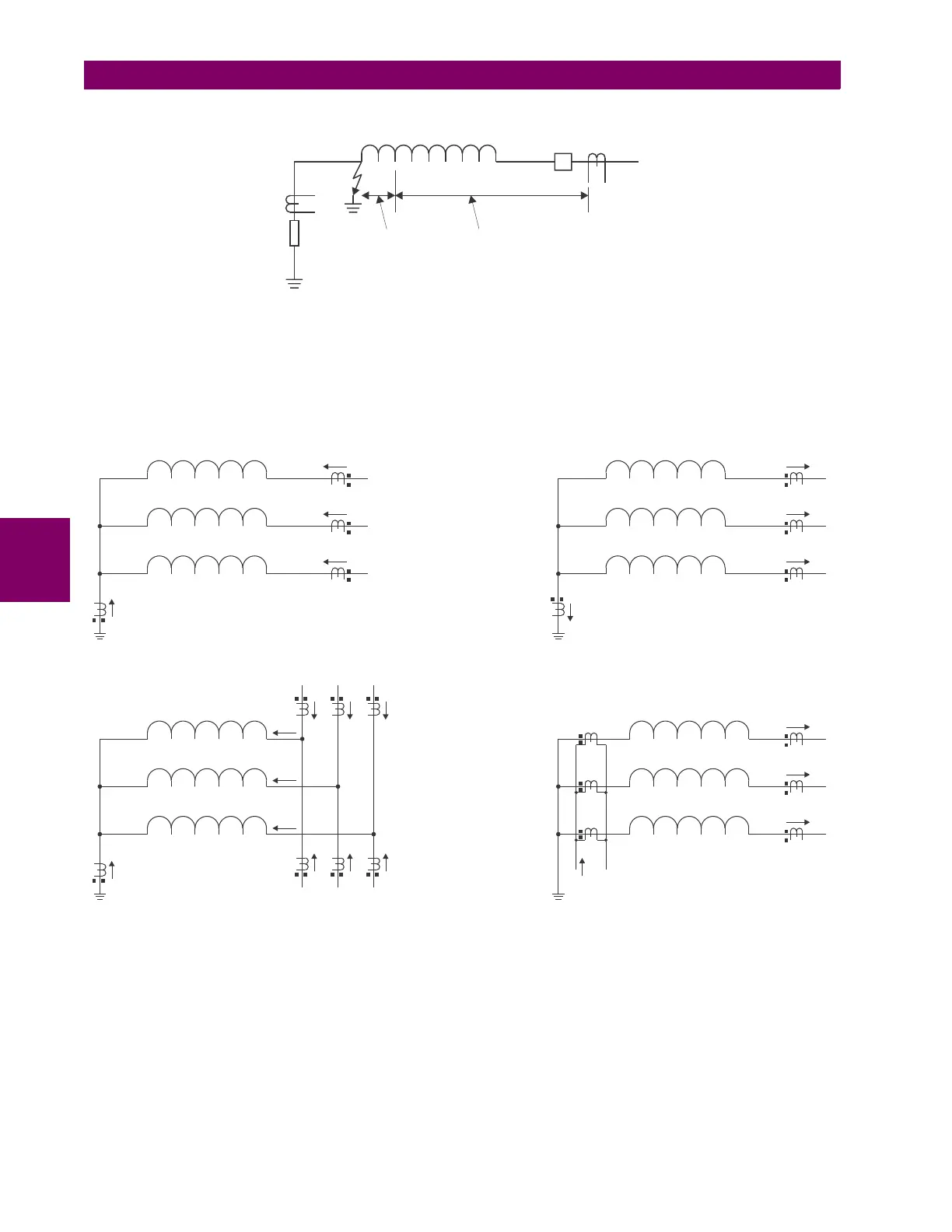
Figure 5–82: RGF AND PERCENT DIFFERENTIAL ZONES OF PROTECTION
This protection is often applied to transformers having impedance-grounded wye windings. The element may also be
applied to the stator winding of a generator having the neutral point grounded with a CT installed in the grounding path, or
the ground current obtained by external summation of the neutral-side stator CTs. The Typical Applications of RGF Protec-
tion diagram explains the basic application and wiring rules.
Figure 5–83: TYPICAL APPLICATIONS OF RGF PROTECTION
The relay incorporates low-impedance restricted ground fault protection. This low-impedance form of protection faces
potential stability problems. An external phase-to-phase fault is an ultimate case. Ideally, there is neither ground (IG) nor
neutral (IN = IA + IB + IC) current present. If one or more of the phase CTs saturate, a spurious neutral current is seen by
the relay. This is similar to a single infeed situation and may be mistaken for an internal fault. Similar difficulties occur in a
breaker-and-a-half application of the restricted ground fault, where any through fault with a weak infeed from the winding
itself may cause problems.
The UR uses a novel definition of the restraining signal to cope with the above stability problems while providing for fast
and sensitive protection. Even with the improved definition of the restraining signal, the breaker-and-a-half application of
the restricted ground fault must be approached with care, and is not recommended unless the settings are carefully
selected to avoid maloperation due to CT saturation.
842731A1.CDR
35%
RGF
ZONE
DIFFERENTIAL ZONE
Rg
WINDING
842732A1.CDR
IG
IG
IA
IA
IB
IB
IC
IC
2
1
2
1
2
1
IG
IG
Transformer Winding
Transformer Winding
(A) Transformer
(B) Transformer in a Breaker-and-a-Half
(C) Stator
(D) Stator without a Ground CT
Stator Winding
Stator Winding
IA
IA
IA
IA
IB
IB
IB
IB
IC
IC
IC
IC