B-48 F60 Feeder Protection System GE Multilin
B.4 MEMORY MAPPING APPENDIX B
B
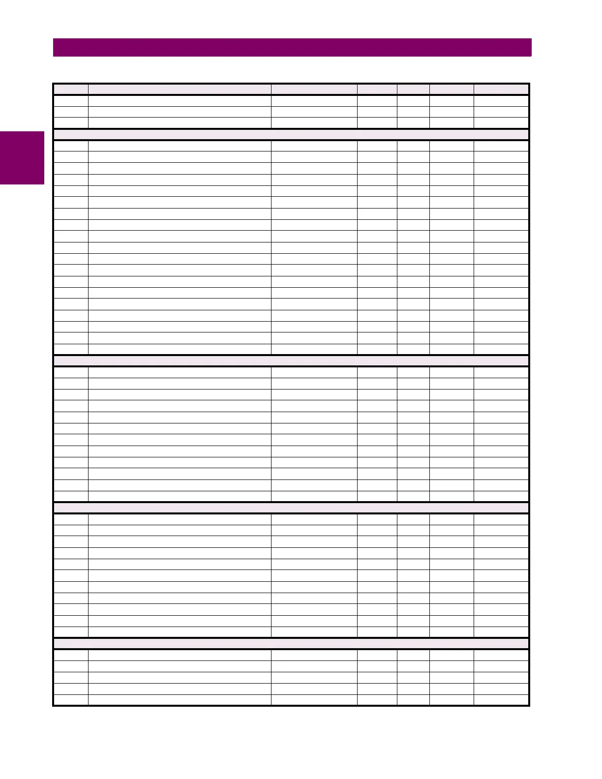
7DD0 ...Repeated for User Programmable Pushbutton 14
7E00 ...Repeated for User Programmable Pushbutton 15
7E30 ...Repeated for User Programmable Pushbutton 16
High Impedance Fault Detection (Hi-Z) Settings (Read/Write Setting)
7E60 Hi-Z Function 0 to 1 --- 1 F102 0 (Disabled)
7E61 Hi-Z Signal Source 0 to 5 --- 1 F167 0 (SRC 1)
7E62 Hi-Z Arcing Sensitivity 1 to 10 --- 1 F001 5
7E63 Hi-Z Phase Event Count 10 to 250 --- 1 F001 30
7E64 Hi-Z Ground Event Count 10 to 500 --- 1 F001 30
7E65 Hi-Z Event Count Time 5 to 180 min 1 F001 15
7E66 Hi-Z Overcurrent Protection Coordination Timeout 10 to 200 s 1 F001 15
7E67 Hi-Z Phase Overcurrent Minimum Pickup 0.01 to 10 pu 0.01 F001 150
7E68 Hi-Z Neutral Overcurrent Minimum Pickup 0.01 to 10 pu 0.01 F001 100
7E69 Hi-Z Phase Rate of Change 1 to 999 A/2cycle 1 F001 150
7E6A Hi-Z Neutral Rate of Change 1 to 999 A/2cycle 1 F001 150
7E6B Hi-Z Loss of Load Threshold 5 to 100 % 1 F001 15
7E6C Hi-Z 3-Phase Event Threshold 1 to 1000 A 1 F001 25
7E6D Hi-Z Voltage Supervision Threshold 0 to 100 % 1 F001 5
7E6E Hi-Z Voltage Supervision Delay 0 to 3000 cycles 2 F001 60
7E6F HIZ Even Harmonic Restraint 0 to 100 % 1 F001 20
7E70 Hi-Z Target 0 to 2 --- 1 F109 0 (Self-reset)
7E71 Hi-Z Events 0 to 1 --- 1 F102 0 (Disabled)
7E72 Hi-Z Arcing Reset Time 0 to 6000 s 0.1 F001 0
Neutral Overvoltage (Read/Write Grouped Setting) (3 modules)
7F00 Neutral Overvoltage 1 Function 0 to 1 --- 1 F102 0 (Disabled)
7F01 Neutral Overvoltage 1 Signal Source 0 to 5 --- 1 F167 0 (SRC 1)
7F02 Neutral Overvoltage 1 Pickup 0 to 3 pu 0.001 F001 300
7F03 Neutral Overvoltage 1 Pickup Delay 0 to 600 s 0.01 F001 100
7F04 Neutral Overvoltage 1 Reset Delay 0 to 600 s 0.01 F001 100
7F05 Neutral Overvoltage 1 Block 0 to 4294967295 --- 1 F300 0
7F07 Neutral Overvoltage 1 Target 0 to 2 --- 1 F109 0 (Self-reset)
7F08 Neutral Overvoltage 1 Events 0 to 1 --- 1 F102 0 (Disabled)
7F09 Neutral Overvoltage 1 Curves 0 to 3 --- 1 F116 0 (Definite Time)
7F0A Reserved (7 items) 0 to 65535 --- 1 F001 0
7F11 ...Repeated for Neutral Overvoltage 2
7F22 ...Repeated for Neutral Overvoltage 3
Auxiliary Undervoltage (Read/Write Grouped Setting (2 modules)
7F60 Auxiliary Undervoltage 1 Function 0 to 1 --- 1 F102 0 (Disabled)
7F61 Auxiliary Undervoltage 1 Signal Source 0 to 5 --- 1 F167 0 (SRC 1)
7F62 Auxiliary Undervoltage 1 Pickup 0 to 3 pu 0.001 F001 700
7F63 Auxiliary Undervoltage 1 Delay 0 to 600 s 0.01 F001 100
7F64 Auxiliary Undervoltage 1 Curve 0 to 1 --- 1 F111 0 (Definite Time)
7F65 Auxiliary Undervoltage 1 Minimum Voltage 0 to 3 pu 0.001 F001 100
7F66 Auxiliary Undervoltage 1 Block 0 to 4294967295 --- 1 F300 0
7F68 Auxiliary Undervoltage 1 Target 0 to 2 --- 1 F109 0 (Self-reset)
7F69 Auxiliary Undervoltage 1 Events 0 to 1 --- 1 F102 0 (Disabled)
7F6A Reserved (7 items) 0 to 65535 --- 1 F001 0
7F71 ...Repeated for Auxiliary Undervoltage 2
Auxiliary Overvoltage (Read/Write Grouped Setting) (2 modules)
7FA0 Auxiliary Overvoltage 1 Function 0 to 1 --- 1 F102 0 (Disabled)
7FA1 Auxiliary Overvoltage 1 Signal Source 0 to 5 --- 1 F167 0 (SRC 1)
7FA2 Auxiliary Overvoltage 1 Pickup 0 to 3 pu 0.001 F001 300
7FA3 Auxiliary Overvoltage 1 Pickup Delay 0 to 600 s 0.01 F001 100
7FA4 Auxiliary Overvoltage 1 Reset Delay 0 to 600 s 0.01 F001 100
Table B–10: MODBUS MEMORY MAP (Sheet 40 of 70)
ADDR REGISTER NAME RANGE UNITS STEP FORMAT DEFAULT