GE Multilin F60 Feeder Protection System B-93
APPENDIX B B.4 MEMORY MAPPING
B
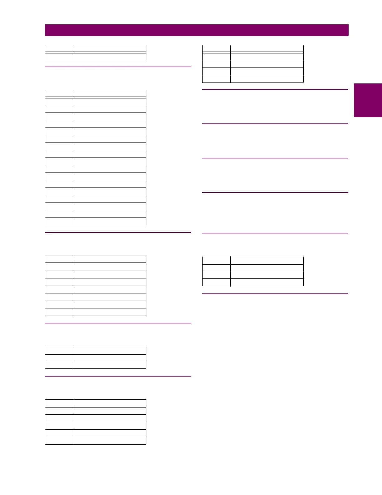
F248
ENUMERATION: BRICK AUX BANK ORIGIN
F253
ENUMERATION: BRICK TRANSDUCER ORIGIN
F254
ENUMERATION: INCIPIENT CABLE FAULT MODE
F256
ENUMERATION: BRICK ORIGIN/DESTINATION
F259
ENUMERATION: BRICK RTD TYPE
0 = 100 Ohm Nickel, 1 = 120 Ohm Nickel, 2 = 100 Ohm Platinum
F260
ENUMERATION: DATA LOGGER MODE
0 = Continuous, 1 = Trigger
F261
ENUMERATION: BANK REDUNDANCY TYPE
0 = None, 1 = Dependability Biased, 2 = Security Biased
F262
ENUMERATION: BRICK STATUS
0 = Disabled, 1 = OK, 2 = Communications Trouble, 3 = Equip-
ment Mismatch, 4 = Brick Trouble
F270
ENUMERATION: FAULT REPORT VT SUBSTITUTION
F300
UR_UINT32: FLEXLOGIC BASE TYPE (15-bit type)
The FlexLogic BASE type is 7 bits and is combined with an 8-bit
descriptor and 1 bit for protection element to form a 16-bit value.
The combined bits are of the form: PTTTTTTTDDDDDDDD,
where P bit if set, indicates that the FlexLogic type is associated
with a protection element state and T represents bits for the BASE
type, and D represents bits for the descriptor.
The values in square brackets indicate the base type with P prefix
[PTTTTTTT] and the values in round brackets indicate the descrip-
tor range. The right-most T bit indicates whether the type is an ON
or OFF type. There can be a total of 64 types (plus protection ele-
ments). There can be a total of 256 descriptors of each type.
[0] Off (0) – this is boolean FALSE value
[1] On (1) – this is boolean TRUE value
[2] CONTACT INPUTS (1 to 96)
[3] CONTACT INPUTS OFF (1 to 96)
[4] VIRTUAL INPUTS (1 to 32)
[6] VIRTUAL OUTPUTS (1 to 64
[8] CONTACT OUTPUTS
[10] CONTACT OUTPUTS VOLTAGE DETECTED (1 to 64)
[11] CONTACT OUTPUTS VOLTAGE OFF DETECTED (1 to 64)
[12] CONTACT OUTPUTS CURRENT DETECTED (1 to 64)
16 U8/AC5..7
Value Description
0None
1U1/AC4
2U1/AC8
3U2/AC4
4U2/AC8
5U3/AC4
6U3/AC8
7U4/AC4
8U4/AC8
9U5/AC4
10 U5/AC8
11 U6/AC4
12 U6/AC8
13 U7/AC5
14 U7/AC8
15 U8/AC5
16 U8/AC8
Value Description
0None
1 U1/DC1
2 U1/DC2
3 U1/DC3
4 U2/DC1
... ...
24 U8/DC3
Value Function
0 Number of Counts
1 Counts per Window
Value Description
0None
1U1
2U2
3U3
4U4
Value Description
5U5
6U6
7U7
8U8
Value Description
0None
1I0
2V0
Value Description