CHAPTER 5: SETPOINTS
489 GENERATOR MANAGEMENT RELAY – INSTRUCTION MANUAL 5–41
Note
The SUPERVISE WITH DIGITAL INPUTS setpoint is seen only if a digital input assigned to
Ground Switch Status.
The 489 detects ground directional by using two measurement quantities: V
0
and I
0
. The
angle between these quantities determines if a ground fault is within the generator or not.
This function should be coordinated with the 59GN element (95% stator ground protection)
to ensure proper operation of the element. Particularly, this element should be faster. This
element must use a core balance CT to derive the I
0
signal. Polarity is critical in this
element. The protection element is blocked for neutral voltages, V
0
, below 2.0 V secondary.
Note
The pickup level for the ground current elements is programmed as a multiple of ground
CT. The 50:0.025 CT is intended for measuring very small ground fault currents when
connected to a sensitive ground CT having the same ratio.
For example, a pickup to 0.2xCT translates into 0.2x0.0025A = 0.5mA secondary on the
terminals of the sensitive ground CT, with a relay measuring 0.2x5A = 1 A primary. A pickup
setting of 0.05xCT would lead to 0.05x0.0025A = 0.125mA secondary, or 0.05x5A =0. 25A
primary current.
It is strongly recommended not to exceed the CT continuous rating of 150mA for long
periods of time during tests.
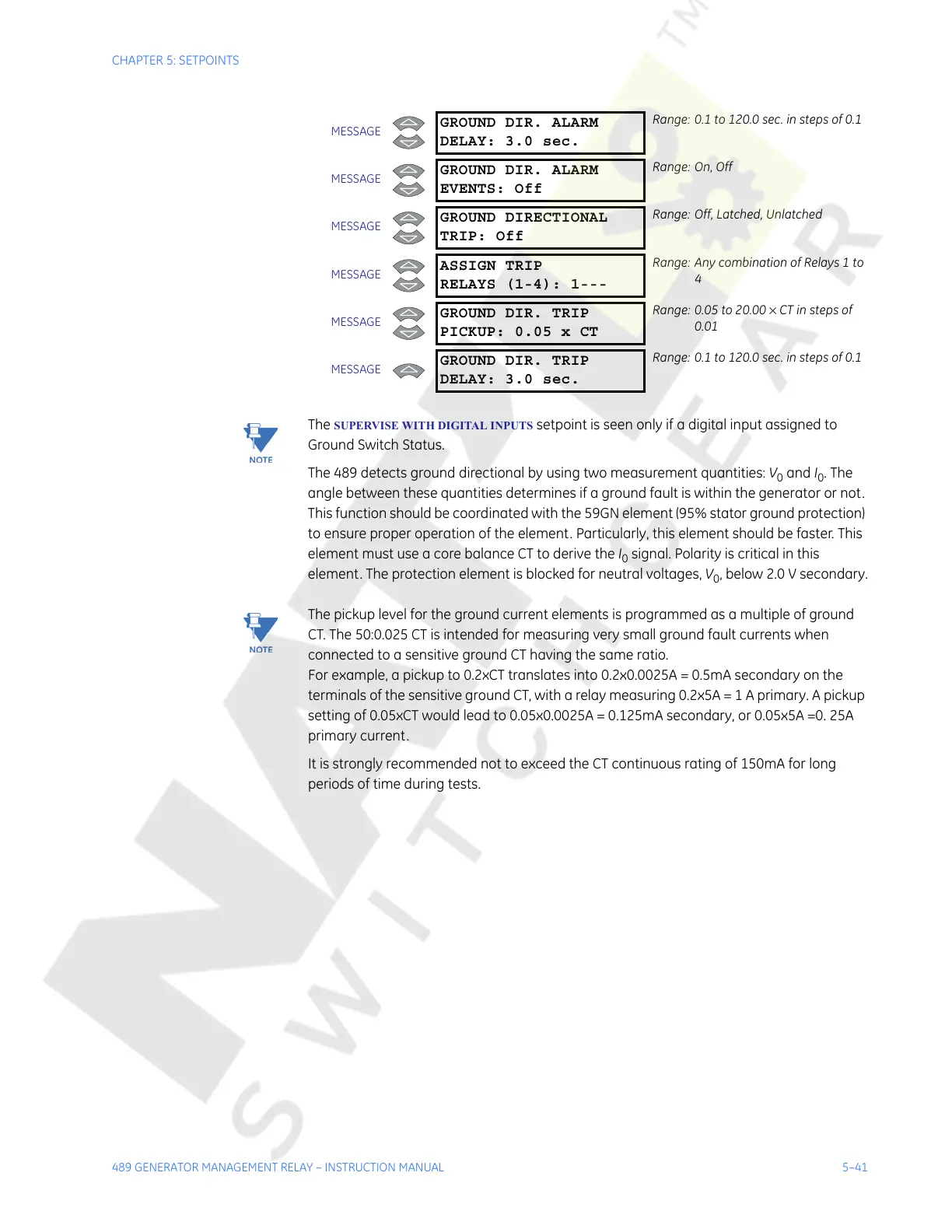
MESSAGE
GROUND DIR. ALARM
DELAY: 3.0 sec.
Range: 0.1 to 120.0 sec. in steps of 0.1
MESSAGE
GROUND DIR. ALARM
EVENTS: Off
Range: On, Off
MESSAGE
GROUND DIRECTIONAL
TRIP: Off
Range: Off, Latched, Unlatched
MESSAGE
ASSIGN TRIP
RELAYS (1-4): 1---
Range: Any combination of Relays 1 to
4
MESSAGE
GROUND DIR. TRIP
PICKUP: 0.05 x CT
Range: 0.05 to 20.00 × CT in steps of
0.01
MESSAGE
GROUND DIR. TRIP
DELAY: 3.0 sec.
Range: 0.1 to 120.0 sec. in steps of 0.1
Courtesy of NationalSwitchgear.com