5–52 489 GENERATOR MANAGEMENT RELAY – INSTRUCTION MANUAL
CHAPTER 5: SETPOINTS
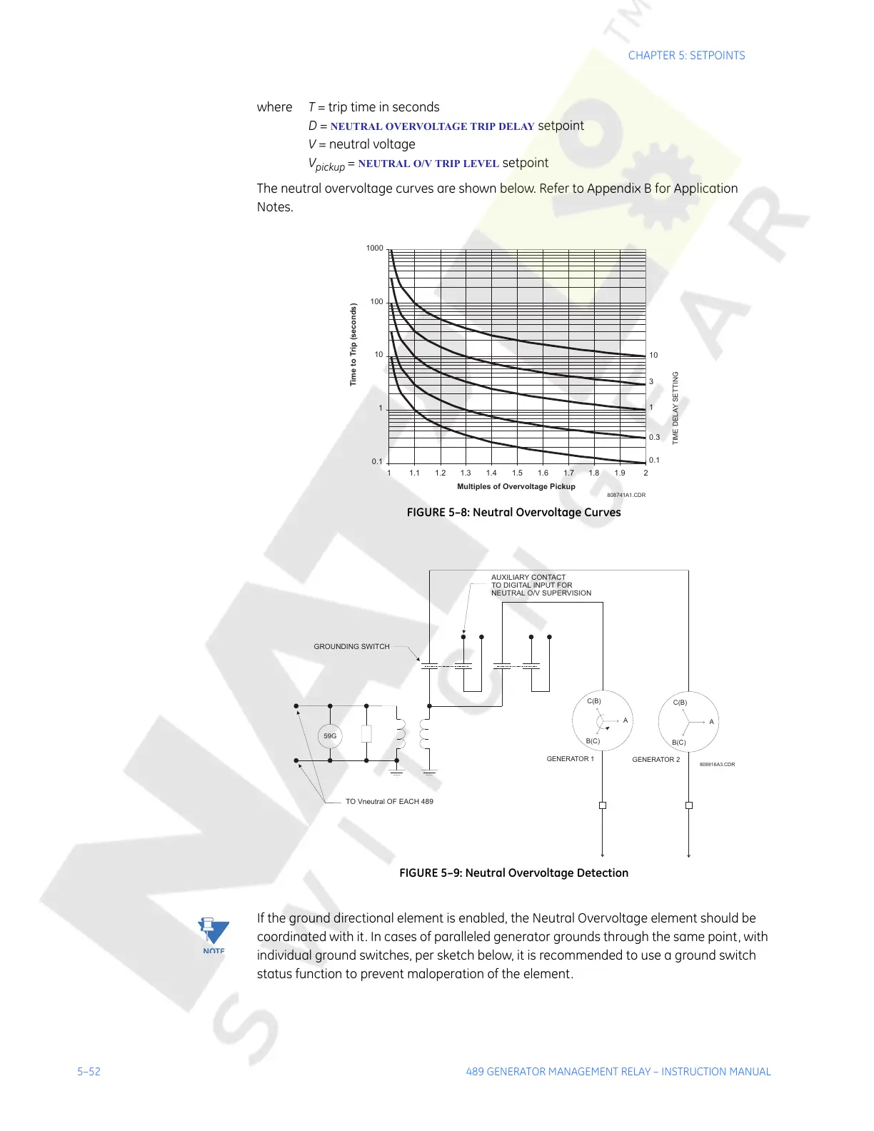
where T = trip time in seconds
D =
NEUTRAL OVERVOLTAGE TRIP DELAY setpoint
V = neutral voltage
V
pickup
= NEUTRAL O/V TRIP LEVEL setpoint
The neutral overvoltage curves are shown below. Refer to Appendix B for Application
Notes.
FIGURE 5–8: Neutral Overvoltage Curves
FIGURE 5–9: Neutral Overvoltage Detection
Note
If the ground directional element is enabled, the Neutral Overvoltage element should be
coordinated with it. In cases of paralleled generator grounds through the same point, with
individual ground switches, per sketch below, it is recommended to use a ground switch
status function to prevent maloperation of the element.
808741A1.CDR
0.1
1
10
100
1000
1 1.1 1.2 1.3 1.4 1.5 1.6 1.7 1.8 1.9 2
Multiples of Overvoltage Pickup
10
3
1
0.3
0.1
Time to Trip (seconds)
TIME DELAY SETTING
59G
A
A
C(B)
C(B)
B(C)
GENERATOR 1
GENERATOR 2
B(C)
TO Vneutral OFEACH489
AUXILIARY CONTACT
TODIGITAL INPUT FOR
NEUTRAL O/V SUPERVISION
GROUNDING SWITCH
808816A3.CDR
Courtesy of NationalSwitchgear.com