CHAPTER 5: SETPOINTS
489 GENERATOR MANAGEMENT RELAY – INSTRUCTION MANUAL 5–77
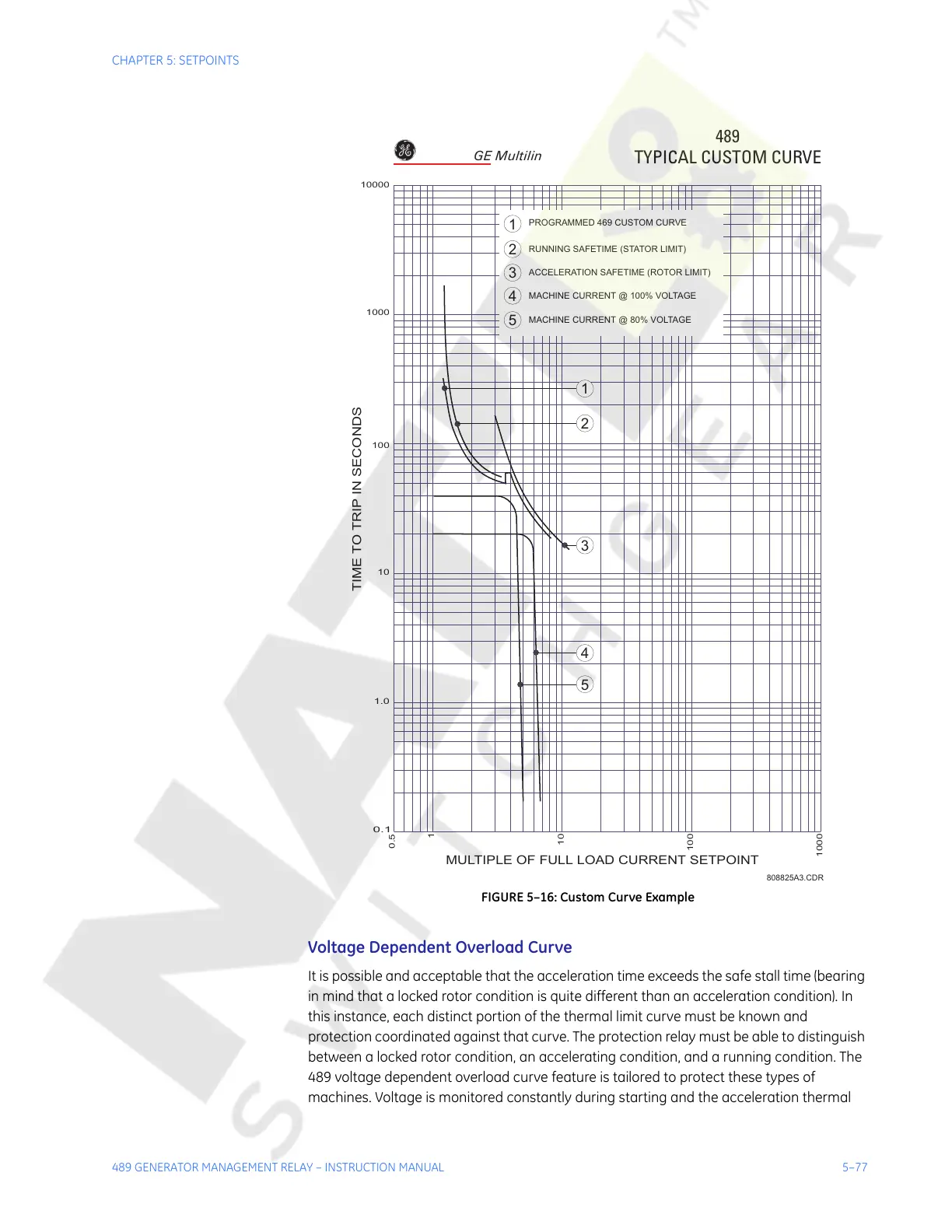
FIGURE 5–16: Custom Curve Example
Voltage Dependent Overload Curve
It is possible and acceptable that the acceleration time exceeds the safe stall time (bearing
in mind that a locked rotor condition is quite different than an acceleration condition). In
this instance, each distinct portion of the thermal limit curve must be known and
protection coordinated against that curve. The protection relay must be able to distinguish
between a locked rotor condition, an accelerating condition, and a running condition. The
489 voltage dependent overload curve feature is tailored to protect these types of
machines. Voltage is monitored constantly during starting and the acceleration thermal
MULTIPLE OF FULL LOAD CURRENT SETPOINT
TIME TO TRIP IN SECONDS
0.1
1.0
10
100
1000
10000
0.5
1
10
100
1000
1
2
3
4
5
2
3
4
5
1
PROGRAMMED 469 CUSTOM CURVE
RUNNING SAFETIME (STATOR LIMIT)
ACCELERATION SAFETIME (ROTOR LIMIT)
MACHINE CURRENT @ 100% VOLTAGE
MACHINE CURRENT @ 80% VOLTAGE
489
TYPICAL CUSTOM CURVE
808825A3.CDR
GE Multilin
Courtesy of NationalSwitchgear.com