7–8 489 GENERATOR MANAGEMENT RELAY – INSTRUCTION MANUAL
CHAPTER 7: TESTING
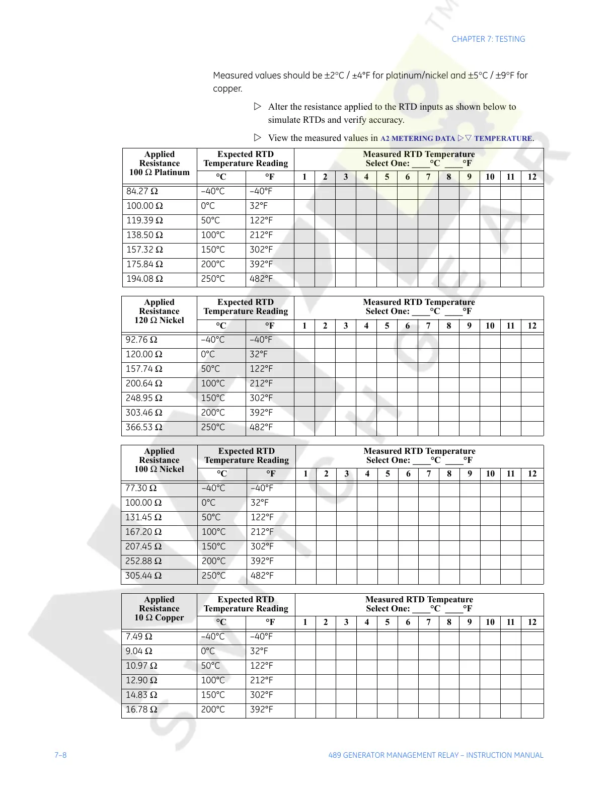
Measured values should be ±2°C / ±4°F for platinum/nickel and ±5°C / ±9°F for
copper.
Z Alter the resistance applied to the RTD inputs as shown below to
simulate RTDs and verify accuracy.
Z View the measured values in
A2 METERING DATA ZV TEMPERATURE.
Applied
Resistance
100 Ω Platinum
Expected RTD
Temperature Reading
Measured RTD Temperature
Select One: ____°C ____°F
°C °F 123456789101112
84.27 Ω –40°C –40°F
100.00 Ω 0°C 32°F
119.39 Ω 50°C 122°F
138.50 Ω 100°C 212°F
157.32 Ω 150°C 302°F
175.84 Ω 200°C 392°F
194.08 Ω 250°C 482°F
Applied
Resistance
120 Ω Nickel
Expected RTD
Temperature Reading
Measured RTD Temperature
Select One: ____°C ____°F
°C °F 123456789101112
92.76 Ω –40°C –40°F
120.00 Ω 0°C 32°F
157.74 Ω 50°C 122°F
200.64 Ω 100°C 212°F
248.95 Ω 150°C 302°F
303.46 Ω 200°C 392°F
366.53 Ω 250°C 482°F
Applied
Resistance
100 Ω Nickel
Expected RTD
Temperature Reading
Measured RTD Temperature
Select One: ____°C ____°F
°C °F 123456789101112
77.30 Ω –40°C –40°F
100.00 Ω 0°C 32°F
131.45 Ω 50°C 122°F
167.20 Ω 100°C 212°F
207.45 Ω 150°C 302°F
252.88 Ω 200°C 392°F
305.44 Ω 250°C 482°F
Applied
Resistance
10 Ω Copper
Expected RTD
Temperature Reading
Measured RTD Tempeature
Select One: ____°C ____°F
°C °F 123456789101112
7.49 Ω –40°C –40°F
9.04 Ω 0°C 32°F
10.97 Ω 50°C 122°F
12.90 Ω 100°C 212°F
14.83 Ω 150°C 302°F
16.78 Ω 200°C 392°F
Courtesy of NationalSwitchgear.com