7–10 489 GENERATOR MANAGEMENT RELAY – INSTRUCTION MANUAL
CHAPTER 7: TESTING
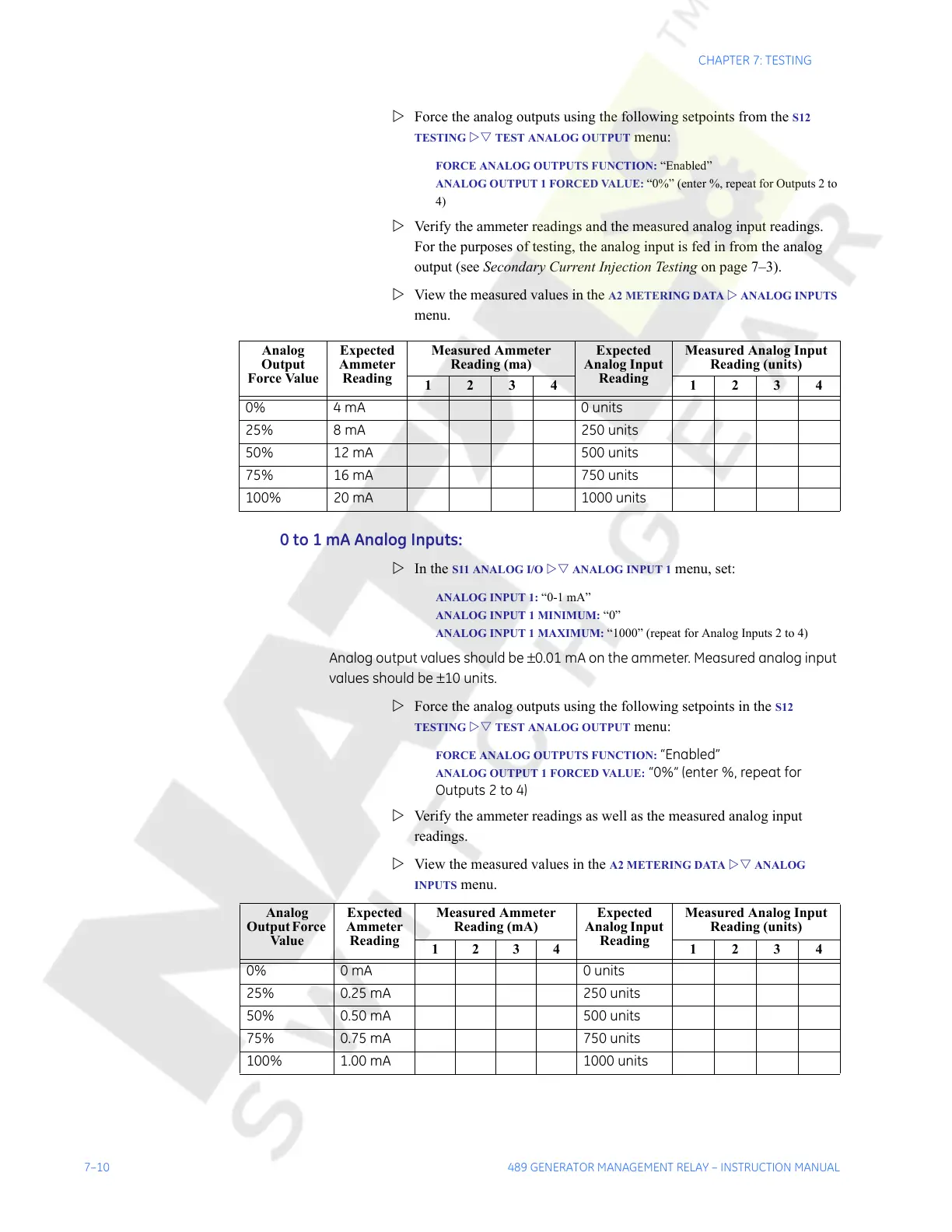
Z Force the analog outputs using the following setpoints from the S12
TESTING
ZV TEST ANALOG OUTPUT menu:
FORCE ANALOG OUTPUTS FUNCTION: “Enabled”
ANALOG OUTPUT 1 FORCED VALUE: “0%” (enter %, repeat for Outputs 2 to
4)
Z Verify the ammeter readings and the measured analog input readings.
For the purposes of testing, the analog input is fed in from the analog
output (see Secondary Current Injection Testing on page 7–3).
Z View the measured values in the
A2 METERING DATA Z ANALOG INPUTS
menu.
0 to 1 mA Analog Inputs:
Z In the S11 ANALOG I/O ZV ANALOG INPUT 1 menu, set:
ANALOG INPUT 1: “0-1 mA”
ANALOG INPUT 1 MINIMUM: “0”
ANALOG INPUT 1 MAXIMUM: “1000” (repeat for Analog Inputs 2 to 4)
Analog output values should be ±0.01 mA on the ammeter. Measured analog input
values should be ±10 units.
Z Force the analog outputs using the following setpoints in the
S12
TESTING ZV TEST ANALOG OUTPUT menu:
FORCE ANALOG OUTPUTS FUNCTION: “Enabled”
ANALOG OUTPUT 1 FORCED VALUE: “0%” (enter %, repeat for
Outputs 2 to 4)
Z Verify the ammeter readings as well as the measured analog input
readings.
Z View the measured values in the
A2 METERING DATA ZV ANALOG
INPUTS menu.
Analog
Output
Force Value
Expected
Ammeter
Reading
Measured Ammeter
Reading (ma)
Expected
Analog Input
Reading
Measured Analog Input
Reading (units)
1234 1234
0% 4 mA 0 units
25% 8 mA 250 units
50% 12 mA 500 units
75% 16 mA 750 units
100% 20 mA 1000 units
Analog
Output Force
Value
Expected
Ammeter
Reading
Measured Ammeter
Reading (mA)
Expected
Analog Input
Reading
Measured Analog Input
Reading (units)
1234 1234
0% 0 mA 0 units
25% 0.25 mA 250 units
50% 0.50 mA 500 units
75% 0.75 mA 750 units
100% 1.00 mA 1000 units
Courtesy of NationalSwitchgear.com