7–18 489 GENERATOR MANAGEMENT RELAY – INSTRUCTION MANUAL
CHAPTER 7: TESTING
Slope 2 Check
Z Set fault current, I
Y
equal to 2.5 × CT.
At this value the relay should operate according to the following formula.
(EQ 7.7)
Z Set fault current, I
x
equal to 0.95 × I
XOP2
.
Z Switch on the test set.
The relay should operate.
Z Switch off the current.
Z Set fault current, I
x
equal to 1.05 × I
XOP2
.
Z Switch on the test set.
The relay should restrain.
Z Switch off the current.
Directional Check
Z Set pre-fault current, I
x
and I
Y
equal to 3.5 × CT.
At this value the conditions for CT saturation detection are set and the
relay will enable the directional check.
Z Set fault current, I
x
equal to 0.95 × I
XOP2
.
Z Switch on the test set.
The relay should restrain.
Z Switch off the current.
Z Repeat steps from Minimum Pickup Check onward for phases B
and C.
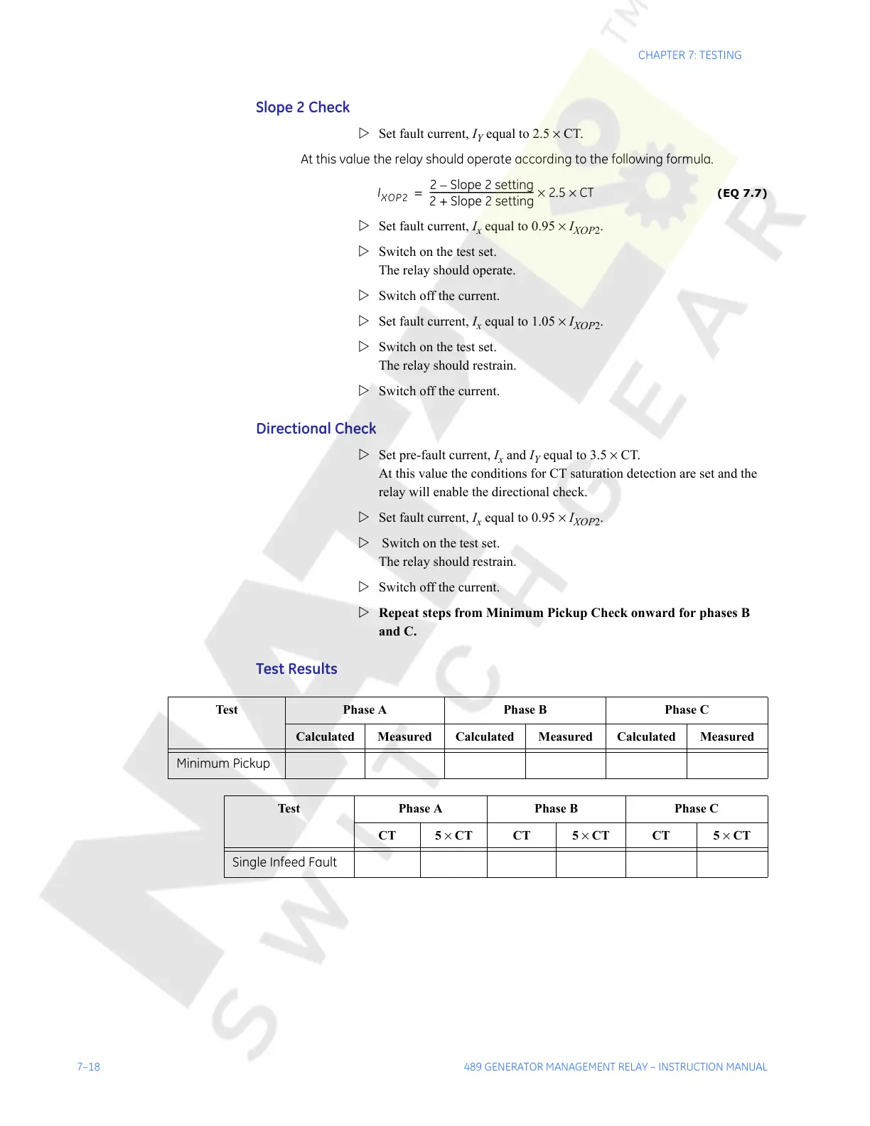
Test Results
I
XOP2
2 Slope 2 setting–
2 Slope 2 setting+
----------------------------------------------
2.5 CT××=
Test Phase A Phase B Phase C
Calculated Measured Calculated Measured Calculated Measured
Minimum Pickup
Test Phase A Phase B Phase C
CT 5 × CT CT 5 × CT CT 5 × CT
Single Infeed Fault
Courtesy of NationalSwitchgear.com