Protection Schemes745
Transformer Management Relay
Commissioning
http://www.GEindustrial.com/multilin
7–16
GE Multilin
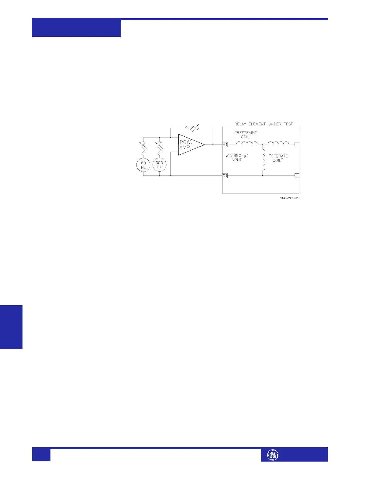
j) 5th Harmonic Restraint
Verifying the operation of the 5th harmonic restraint requires test equipment
capable of generating a current signal containing a fundamental and 5th harmonic.
Most modern dedicated relay test instruments, such as Powertec's (or Manta) DFR,
Doble, or MultiAmp instruments are capable of generating appropriate signals. A
power operational amplifier with a suitably rated output, or a power audio amplifier,
may also be used to generate the appropriate signal.
1. Connect the test setup as below to supply the Phase A element. Set the funda-
mental current level to the CT rated secondary value. The harmonic restraint
differential element of Phase A should be operated.
FIGURE 7–8: 5th Harmonic Restraint Testing
2. Increase the 5th harmonic component to a value well above the
S4 ELEMENTS
!" DIFFERENTIAL !" 5TH HARM INHIBIT !" 5TH HARMONIC INHIBIT LEVEL setting.
3. Remove the total current signal and reapply. The relay should not operate.
Decrease the 5th harmonic component until the element operates.
4. Calculate the percentage 5th harmonic to restrain from the following equation:
(EQ 7.14)
5. Compare this value to the relay setting.
k) Energization Detection Scheme
Refer to Differential Element on page 5–41 for a description of this feature. This
feature is activated by up to three inputs: breaker auxiliary switch, current below a
threshold, or absence of voltage. The procedure below tests the current-level
enabling feature. A similar approach can verify the other two enabling functions with
the proper test equipment.
1. Enable the Energization Detection Scheme by setting
S4 ELEMENTS !" DIFFEREN-
TIAL !" ENERGIZATION INHIBIT ! ENERGIZATION INHIBIT FUNCTION to “Enabled”.
2. Make the following setpoint changes in the
S4 ELEMENTS !" DIFFERENTIAL !"
ENERGIZATION INHIBIT setpoints menu:
ENERGIZATION INHIBIT PARMETERS: “2nd”
HARMONIC AVERAGING: “Disabled”
ENERGIZATION INHIBIT LEVEL: “15%”
ENERGIZATION INHIBIT DURATION: “5 s”
ENERGIZATION SENSING BY CURRENT: “Enabled”
ENERGIZATION INHIBIT/MINIMUM ENERGIZATION CURRENT: “0.10 × CT”
3. Preset current with harmonic content just above the
ENERGIZATION INHIBIT LEVEL
used during the ‘energization period’. Apply the current signal and measure the
operating time. The time should be equal to ‘energization period’ plus
approximately 50 ms.
%5th
100 level of 5th harmonic×
level of fundamental
---------------------------------------------------------------------------------=