Drawout Case745
Transformer Management Relay
Installation
http://www.GEindustrial.com/multilin
3–4
GE Multilin
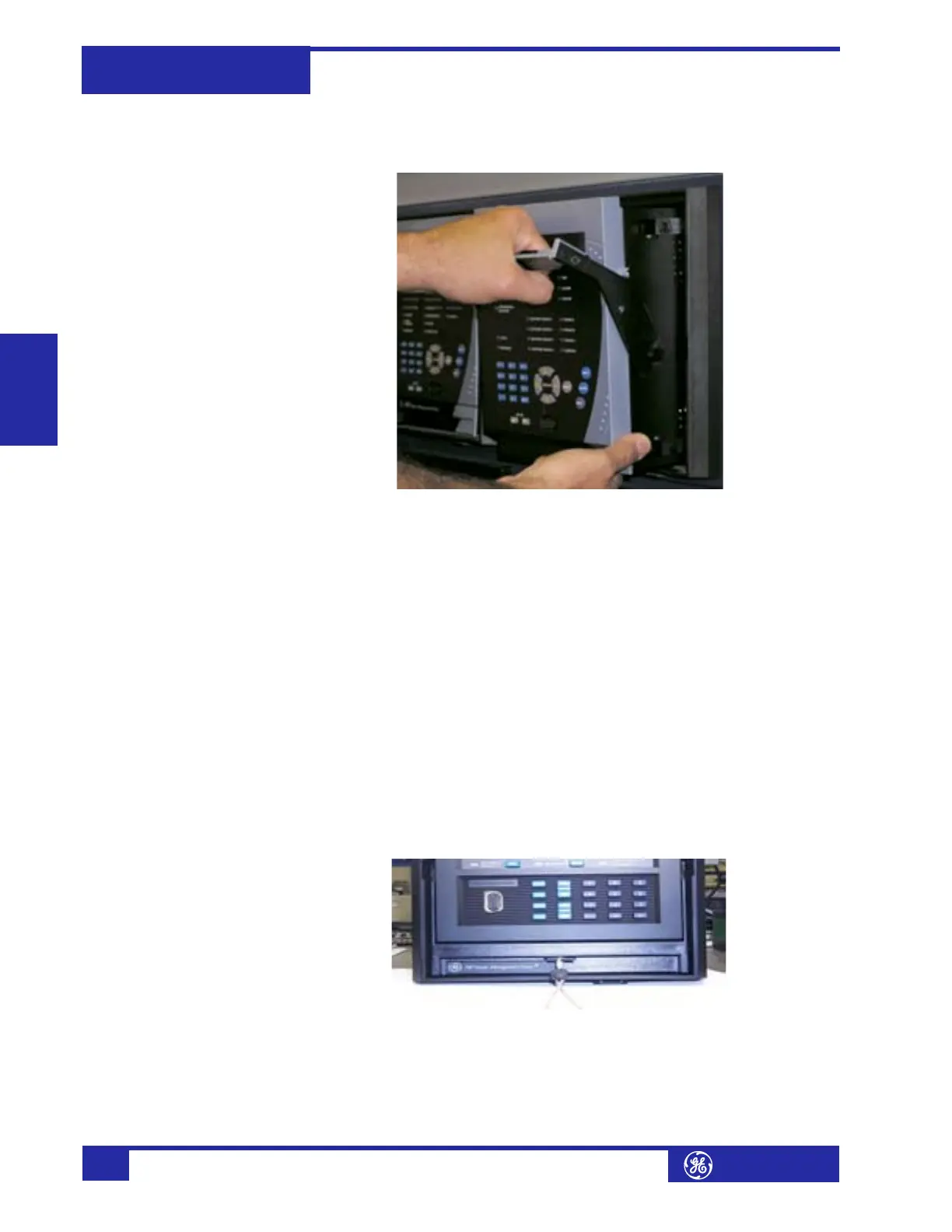
4. Once the handle is released from the locking mechanism, the unit can freely
slide out of the case when pulled by the handle. It may sometimes be necessary
to adjust the handle position slightly to free the unit.
FIGURE 3–7: Slide Unit out of Case
To insert the unit into the case:
1. Raise the locking handle to the highest position.
2. Hold the unit immediately in front of the case and align the rolling guide pins
(near the hinges of the locking handle) to the guide slots on either side of the
case.
3. Slide the unit into the case until the guide pins on the unit have engaged the
guide slots on either side of the case.
4. Grasp the locking handle from the center and press down firmly, rotating the
handle from the raised position toward the bottom of the unit.
5. When the unit is fully inserted, the latch will be heard to click, locking the han-
dle in the final position.
To prevent unauthorized removal of the drawout unit, a wire lead seal can be
installed in the slot provided on the handle as shown below. With this seal in place,
the drawout unit cannot be removed. A passcode or setpoint access jumper can be
used to prevent entry of setpoints but still allow monitoring of actual values. If
access to the front panel controls must be restricted, a separate seal can be
installed on the outside of the cover to prevent it from being opened.
FIGURE 3–8: Drawout Unit Seal