3-50 G60 Generator Protection System GE Multilin
3.4 FIELD AND STATOR GROUND MODULES 3 HARDWARE
3
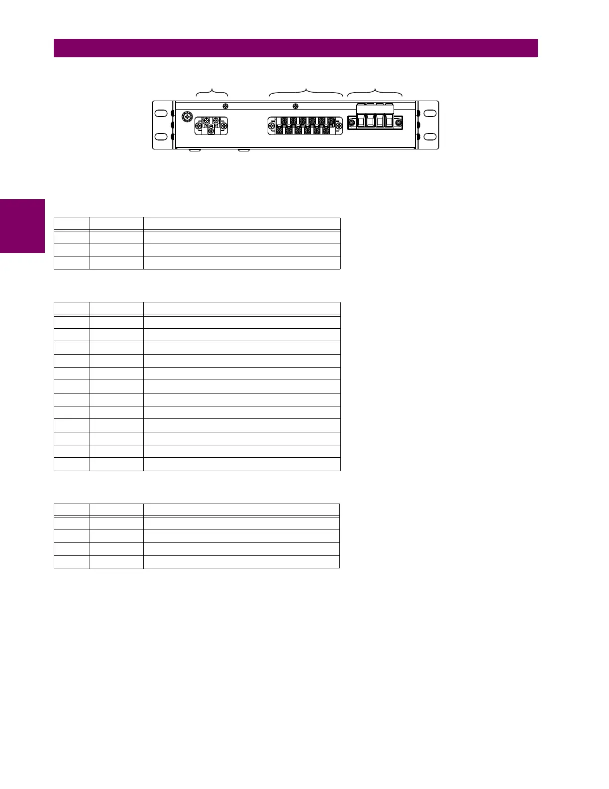
Figure 3–60: REAR VIEW OF GPM-F-HM MODULE SHOWING TERMINAL BLOCKS
The pin assignments are described in the following tables.
There are three connectors on the field ground protection high-voltage resistor box as shown below.
Table 3–9: GPM-F-HM PIN ASSIGNMENTS FOR CONNECTOR A
PIN LABEL DEFINITION
1 L(+) AC-L (DC+)
2 N(–) AC-N (DC–)
3 GND Ground
Table 3–10: GPM-F-HM PIN ASSIGNMENTS FOR CONNECTOR B
PIN LABEL DEFINITION
1 CH1(+) RS485 channel 1 positive
2 CH1(–) RS485 channel 1 negative
3 COM RS485 common
4 CH2(+) RS485 channel 2 positive
5 CH2(–) RS485 channel 2 negative
6 IN3 Contact input 3
7 IN2 Contact input 2
8 IN1 Contact input 1
9 COM Contact input common
10 NC Relay NC (normally closed)
11 COM Relay common
12 NO Relay NO (normally open)
Table 3–11: GPM-F-HM PIN ASSIGNMENTS FOR CONNECTOR C
PIN LABEL DEFINITION
1 FGND Field ground
2 F1 Injection to excitation positive
3 F(–) Injection to excitation negative / excitation negative
4 F(+) Excitation positive
&RQQHFWRU$ &RQQHFWRU% &RQQHFWRU&
$&'5

 Loading...


